ZHCSAI5C November   2012  – November 2021

PRODUCTION DATA  

  1. 特性
  2. 应用
  3. 说明
  4. Revision History
  5. Device Comparison Table
  6. Pin Configuration and Functions
  7. Specifications
    1. 7.1  Absolute Maximum Ratings
    2. 7.2  ESD Ratings
    3. 7.3  Recommended Operating Conditions
    4. 7.4  Thermal Information
    5. 7.5  Electrical Characteristics: Supply Current
    6. 7.6  Digital Input and Output DC Characteristics
    7. 7.7  Power-on Reset
    8. 7.8  2.5-V LDO Regulator
    9. 7.9  Internal Clock Oscillators
    10. 7.10 ADC (Temperature and Cell Measurement) Characteristics
    11. 7.11 Integrating ADC (Coulomb Counter) Characteristics
    12. 7.12 Data Flash Memory Characteristics
    13. 7.13 I2C-Compatible Interface Communication Timing Requirements
    14. 7.14 Typical Characteristics
  8. Detailed Description
    1. 8.1 Overview
    2. 8.2 Functional Block Diagram
    3. 8.3 Feature Description
    4. 8.4 Device Functional Modes
      1. 8.4.1 Power Modes
        1. 8.4.1.1 BAT INSERT CHECK Mode
        2. 8.4.1.2 NORMAL Mode
        3. 8.4.1.3 SLEEP Mode
      2. 8.4.2 SLEEP+ Mode
      3. 8.4.3 HIBERNATE Mode
    5. 8.5 Programming
      1. 8.5.1 Standard Data Commands
      2. 8.5.2 Extended Data Commands
      3. 8.5.3 Communications
        1. 8.5.3.1 I2C Interface
        2. 8.5.3.2 I2C Time Out
        3. 8.5.3.3 I2C Command Waiting Time
        4. 8.5.3.4 I2C Clock Stretching
  9. Application and Implementation
    1. 9.1 Application Information
    2. 9.2 Typical Application
      1. 9.2.1 Design Requirements
      2. 9.2.2 Detailed Design Procedure
        1. 9.2.2.1 BAT Voltage Sense Input
        2. 9.2.2.2 SRP and SRN Current Sense Inputs
        3. 9.2.2.3 Sense Resistor Selection
        4. 9.2.2.4 TS Temperature Sense Input
        5. 9.2.2.5 Thermistor Selection
        6. 9.2.2.6 REGIN Power Supply Input Filtering
        7. 9.2.2.7 VCC LDO Output Filtering
      3. 9.2.3 Application Curves
  10. 10Power Supply Recommendations
    1. 10.1 Power Supply Decoupling
  11. 11Layout
    1. 11.1 Layout Guidelines
      1. 11.1.1 Sense Resistor Connections
      2. 11.1.2 Thermistor Connections
      3. 11.1.3 High-Current and Low-Current Path Separation
    2. 11.2 Layout Example
  12. 12Device and Documentation Support
    1. 12.1 第三方产品免责声明
    2. 12.2 Documentation Support
      1. 12.2.1 Related Documentation
    3. 12.3 接收文档更新通知
    4. 12.4 支持资源
    5. 12.5 Trademarks
    6. 12.6 Electrostatic Discharge Caution
    7. 12.7 术语表
  13. 13Mechanical, Packaging, and Orderable Information

封装选项

机械数据 (封装 | 引脚)
散热焊盘机械数据 (封装 | 引脚)
订购信息

说明

德州仪器 (TI) BQ27520-G4 系统侧锂离子电池电量监测计是一款微控制器外设,能够提供针对单节锂离子电池组的电量监测。此器件只需很少的系统微控制器固件开发。此电量监测计位于系统主板上,可管理嵌入式电池(不可拆卸)或可拆卸电池组。

此电量监测计使用获得专利的 Impedance Track™ 算法来进行电量监测,可提供剩余电池电量 (mAh)、充电状态 (%)、续航时间(最小值)、电池电压 (mV)、温度 (°C) 和运行状况 (%) 等信息。

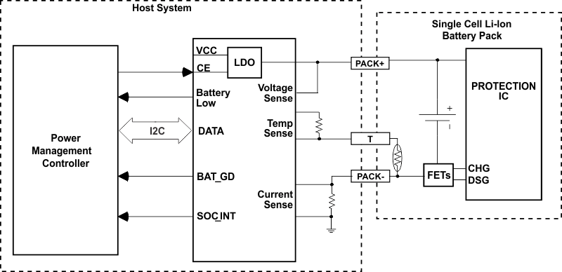
进行电池电量监测时,只需将 PACK+ (P+)、PACK- (P-) 以及可选的热敏电阻 (T) 连接至一个可拆卸电池组或嵌入式电池电路。该器件采用 15 焊球 NanoFree™ (DSBGA) 封装,其标称尺寸为
2610 × 1956µm,引线间距为 0.5mm。它是空间受限类应用的理想选择。

器件信息
器件型号 封装(1) 封装尺寸(标称值)
BQ27520-G4 DSBGA (15) 2.610 mm × 1.956 mm
如需了解所有可用封装,请参阅数据表末尾的可订购产品附录。
GUID-5898120A-DB2F-413D-80D2-F1636CE47D7C-low.gif典型应用图