TIDT196 September 2020 – MONTH
1 Description
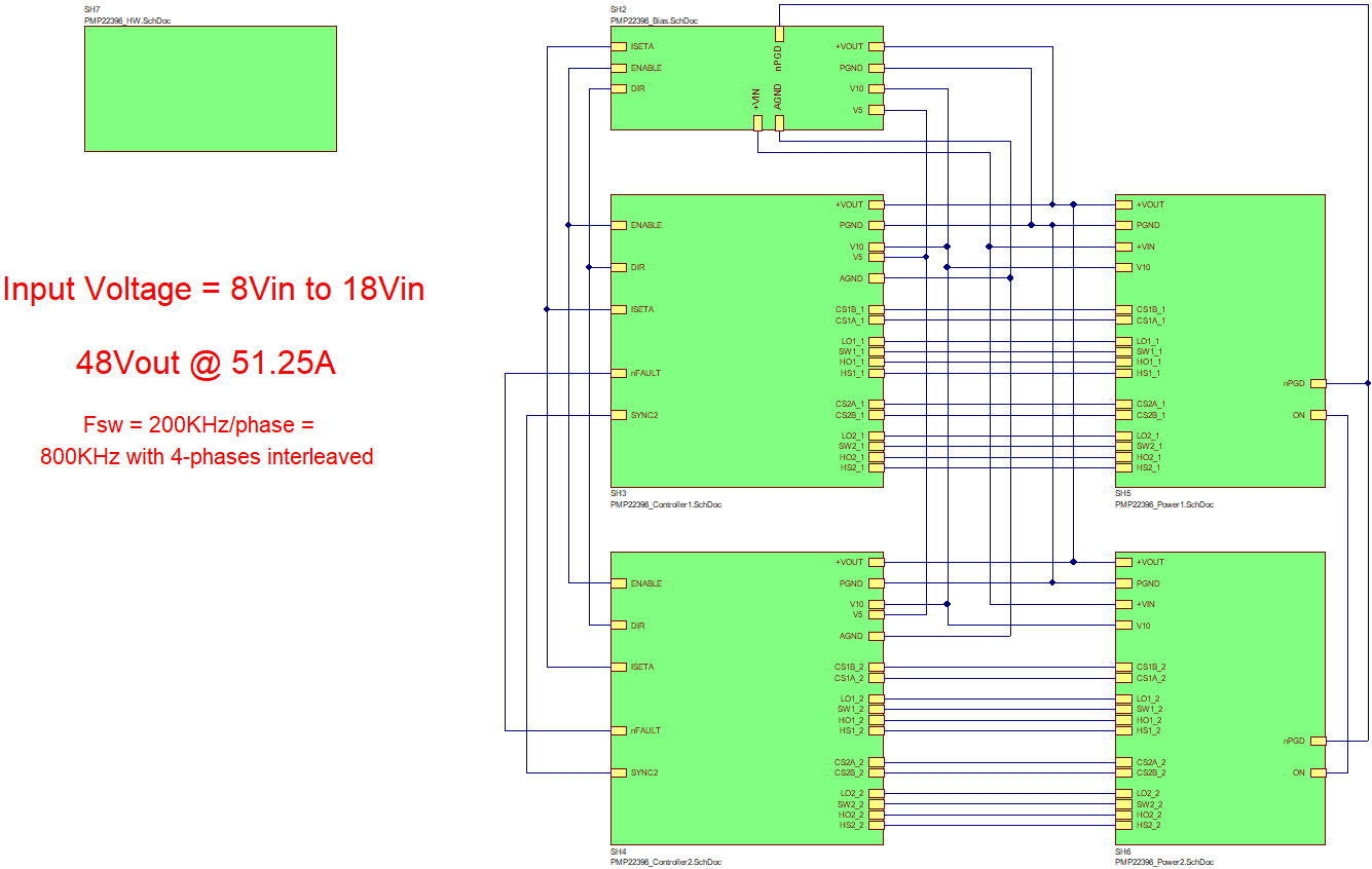
This reference design is a 2460-W bidirectional boost converter for automotive applications. The circuit is powered from the nominal 12-V battery to provide an output voltage of 48 V at 51.25 A. The design uses two dual-phase synchronous bidirectional controllers operating at a switching frequency of 200 kHz per phase. The 48-V output is designed to drive a motor. When the load current reverses and the output voltage reaches 54 V, hysteretic direction control allows the load current to be returned to the 12-V battery. Normal boost operation resumes when the output voltage returns to 48 V. Mounting holes are provided for a bottom-side heat sink underneath the MOSFETs.
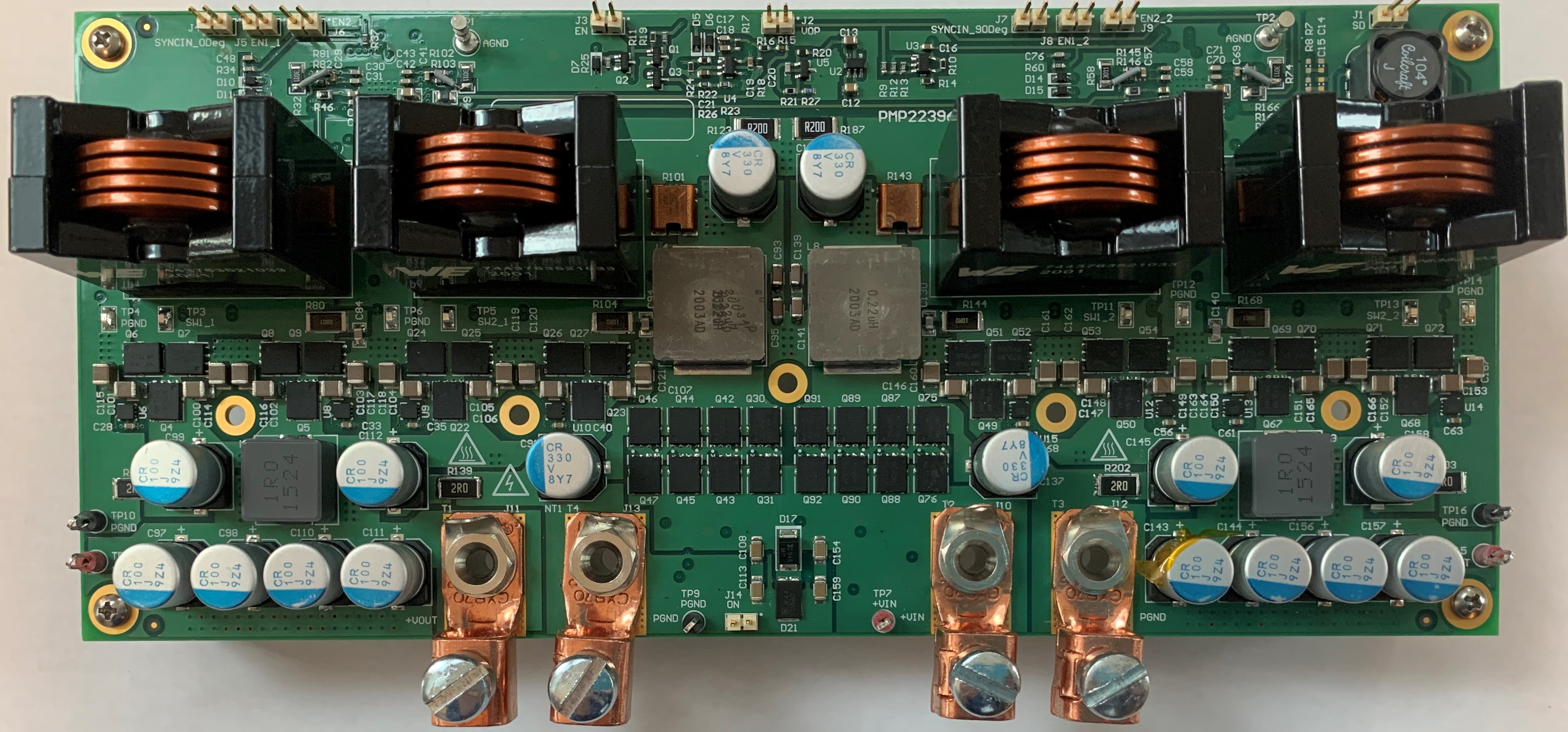
 Figure 1-1 Top Photo
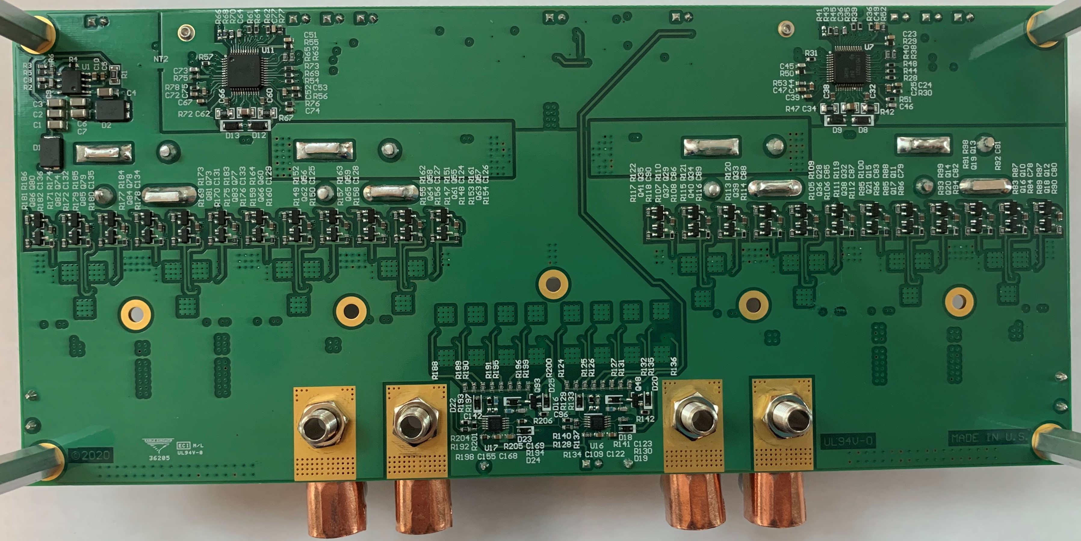
 Figure 1-2 Bottom Photo
 Figure 1-3 Block Diagram