TIDT196 September 2020 – MONTH
2.5 Test Setup
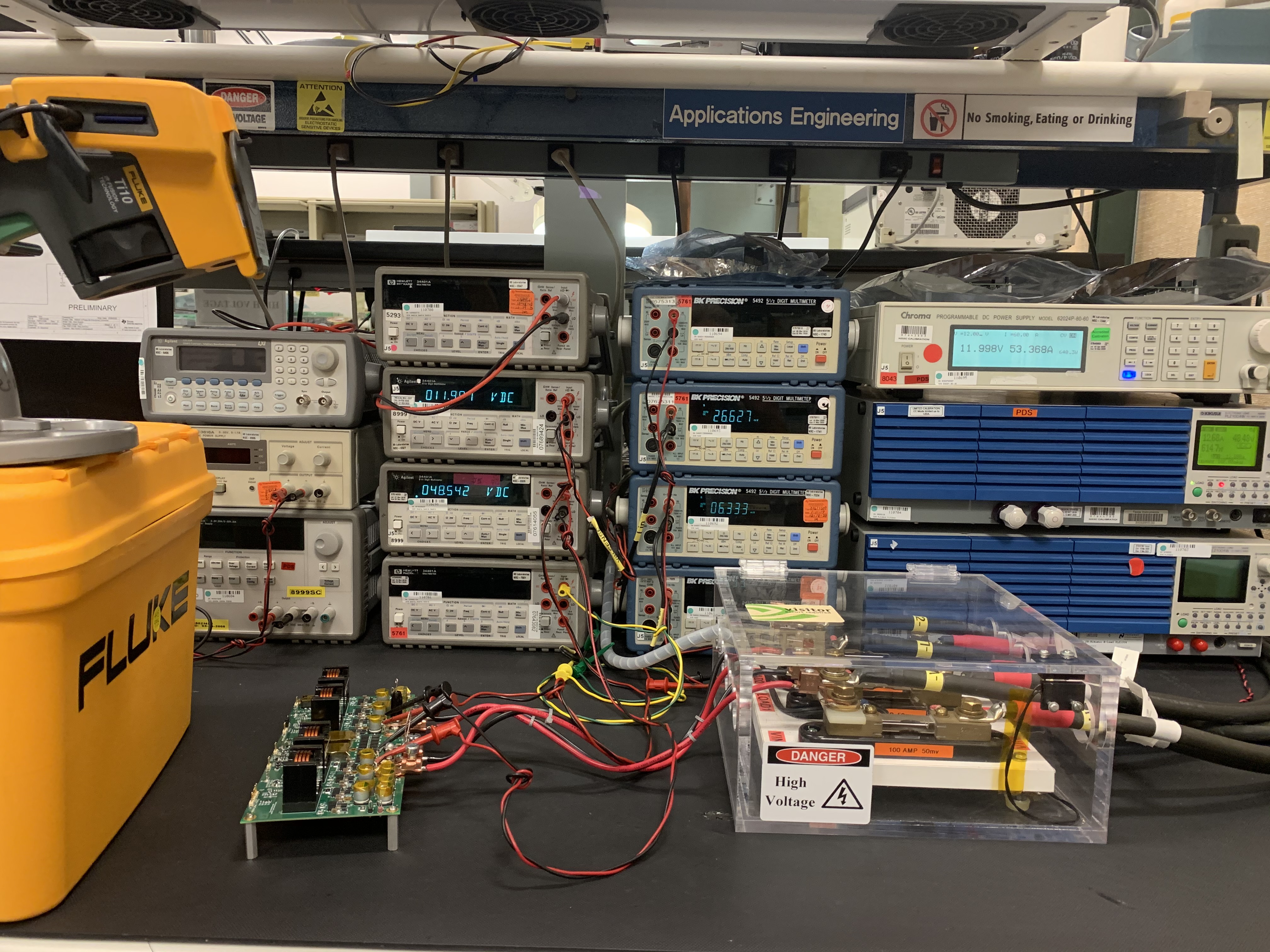
The test setup is shown in the following picture. All tests were performed at room temperature on an open bench.
 Figure 2-1 Test Setup
TIDT196 September 2020 – MONTH
The test setup is shown in the following picture. All tests were performed at room temperature on an open bench.
 Figure 2-1 Test Setup