SPRUJ74 January 2023
2.2.1 Detailed Board Assembly Procedure (J784S4XG01EVM)
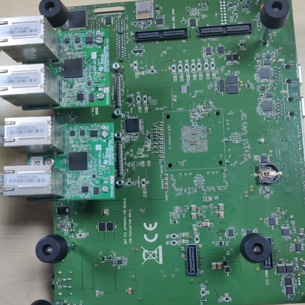
This assembly procedure example is given for mating the QP-ENET board with the J784S4XG01EVM board.
- Take the Assembled J784S4XG01EVM Board
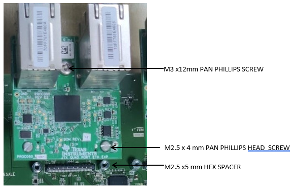
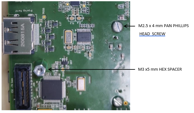
- Add M2.5 x 5mm hex spacers on each mounting holes provided on either sides of the J51 & J52 connector of the J784S4XG01EVM and secure it with M2.5 x 4 mm Phillips screws from the bottom sides to hold the spacer in place.
- Add M3 x 12mm Phillips screws through the mounting hole provided between the Ethernet connectors on the QP ENET board (shown in the picture below) and secure it with a M3 x 5mm hex spacer from the other side (this step is done only on the QP ENET board).
- Mount the QP board onto the J784S4XG01EVM connectors J51 & J52, making sure the connectors are seated evenly.
- Add M2.5 x 4 mm Phillips screws from the top side of the QP to secure the QP mating with the J784S4XG01EVM board.
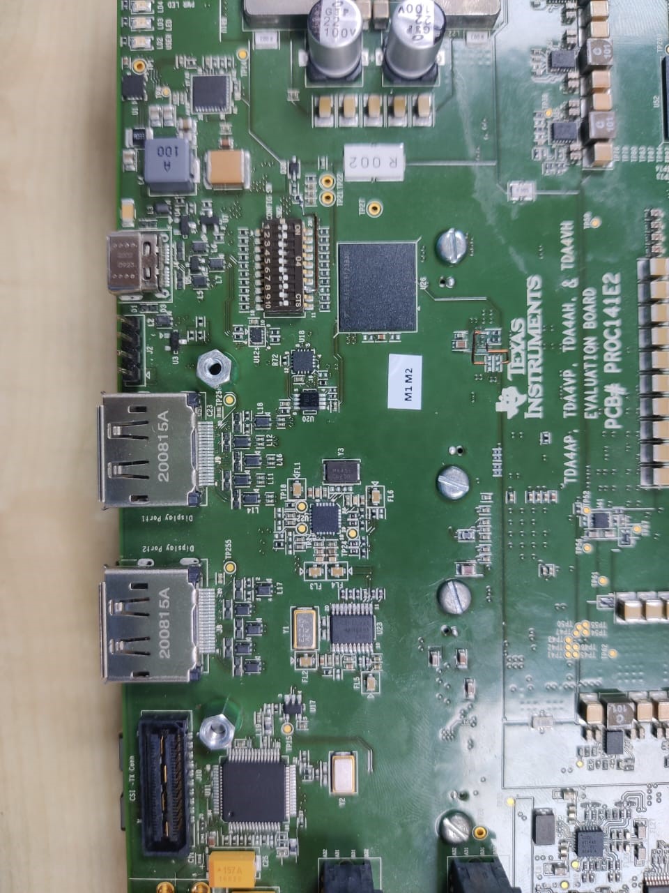
- Add the M2.5 x 5 mm male to male spacer from the top side of the J784S4XG01EVM board to secure the remaining M3 screw protruding from the QP.
- Add a M3 x 5mm spacer from the top side of the J784S4XG01EVM board to lock the other end of the M3 x12mm Phillips screw.
 Figure 2-4 QP ENET Board
 Figure 2-5 Bottom Side of
J784S4XG01EVM
 Figure 2-6 Top Side of
J784S4XG01EVM
 Figure 2-7 J784S4XG01EVM - QP ENET Board
Assembly Procedure