SPRACU9 October 2021 F29H850TU , F29H859TU-Q1 , TMS320F2800152-Q1 , TMS320F2800153-Q1 , TMS320F2800154-Q1 , TMS320F2800155 , TMS320F2800155-Q1 , TMS320F2800156-Q1 , TMS320F2800157 , TMS320F2800157-Q1 , TMS320F280033 , TMS320F280034 , TMS320F280034-Q1 , TMS320F280036-Q1 , TMS320F280036C-Q1 , TMS320F280037 , TMS320F280037-Q1 , TMS320F280037C , TMS320F280037C-Q1 , TMS320F280038-Q1 , TMS320F280038C-Q1 , TMS320F280039 , TMS320F280039-Q1 , TMS320F280039C , TMS320F280039C-Q1 , TMS320F28384D , TMS320F28384D-Q1 , TMS320F28384S , TMS320F28384S-Q1 , TMS320F28386D , TMS320F28386D-Q1 , TMS320F28386S , TMS320F28386S-Q1 , TMS320F28388D , TMS320F28388S , TMS320F28P550SG , TMS320F28P550SJ , TMS320F28P559SG-Q1 , TMS320F28P559SJ-Q1 , TMS320F28P650DH , TMS320F28P650DK , TMS320F28P650SH , TMS320F28P650SK , TMS320F28P659DH-Q1 , TMS320F28P659DK-Q1 , TMS320F28P659SH-Q1
2 Useful tips to run the C2000ware examples
On devices like TMS320F2838xD and TMS320F2838xS, the MCAN module may be controlled either by CPU1 (28x) or the Connectivity Manager ( M4). This is not applicable for devices with only a 28x CPU. Below are some useful tips for a successful run of the examples:
- For TMS320F2838xD and TMS320F2838xS devices, there may be two versions of some examples, a version that runs on CPU1 (28x) and another that runs on CM (M4). For example, in C2000ware version 3.04, CPU1 examples reside in C:\ti\c2000\C2000Ware_3_04_00_00\driverlib\f2838x\examples\c28x\mcan and the CM examples reside in C:\ti\c2000\C2000Ware_3_04_00_00\driverlib\f2838x\examples\cm\mcan. The projects have the same name, so they cannot exist together in the same CCS workspace. Before running any code on the M4 processor, the file cm_common_config_c28x.c should first be executed.
- For the examples to run successfully, it is very important to ensure the clock settings are correct. This is based on the input clock to the device. For details, see below note in the device.c file.
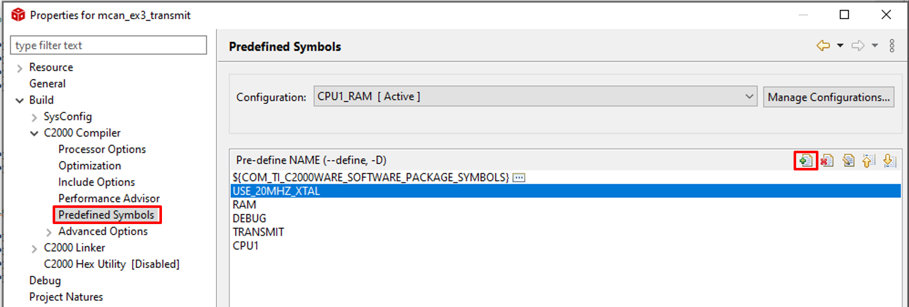
"By default, the Device_init function assumes 25 MHz XTAL. If a 20 MHz crystal is used, add a predefined symbol "USE_20MHZ_XTAL" in your CCS project. If a different XTAL is used, please update the DEVICE_SETCLOCK_CFG macro accordingly. For example, if you are running the examples on a board with a 20 MHz input clock to the MCU, make sure USE_20MHZ_XTAL is added to the predefined symbols". For details, see Figure 2-1.
 Figure 2-1 Adding the Predefined Symbol
in Project Properties
Figure 2-1 Adding the Predefined Symbol
in Project PropertiesIf you convert a RAM-based example to a Flash based example, it is important to once again add the USE_20MHZ_XTAL symbol for the flash-based project as well.
- GPIO configuration: Considering the MCAN signals can be routed to multiple pins, it is important to ensure the correct options are chosen based on your board design. By default, GPIO30 and GPIO31 are chosen for the MCAN function. The following settings are in the device.h file :
#define DEVICE_GPIO_CFG_MCANRXA    GPIO_30_MCAN_RX  // "pinConfig" for MCAN RX
#define DEVICE_GPIO_CFG_MCANTXA    GPIO_31_MCAN_TX  // "pinConfig" for MCAN TX
GPIO_30_MCAN_RX & GPIO_31_MCAN_TX are defined in pin_map.h
- It is possible to communicate between MCAN and eCAN or DCAN, if FDF and BRS bits are disabled. In this case, only classic CAN frames can be used.