SNLU273 December 2020
- Trademarks
- 1Introduction
-
2Description
- 2.1 DS160PR810 4-Level I/O Control Inputs
- 2.2 DS160PR810 Modes of Operation
- 2.3 DS160PR810 SMBus or I2C Register Control Interface
- 2.4 DS160PR810 Equalization Control
- 2.5 DS160PR810 RX Detect State Machine
- 2.6 DS160PR810 DC Gain Control
- 2.7 DS160PR810 EVM Global Controls
- 2.8 DS160PR810EVM Downstream Devices Control
- 2.9 DS160PR810EVM Upstream Devices Control
- 2.10 Quick-Start Guide (Pin Mode)
- 2.11 Quick-Start Guide (SMBus Slave Mode)
- 3Test Setup and Results
- 4Schematics
- 5Board Layout
- 6Bill of Materials
- 7References
3 Test Setup and Results
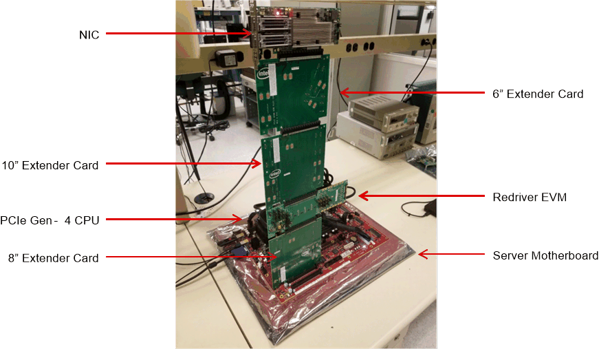
Figure 3-1 shows a typical system setup with the DS160PR810EVM-RSC placed between a CPU on a server motherboard and an PCIe end point (Network Interface Card or NIC). Additional "Extender" cards are inserted to increase the channel loss and demonstrate the ability of the redriver to extend the reach.
 Figure 3-1 Example Test Setup
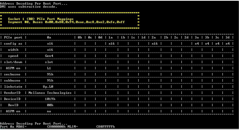
Figure 3-2 is a typical test result achieved with a system shown in Figure 3-1. As the result indicates, the end point (Mellanox NIC) with the DS160PR810EVM-RSC placed in the datapath achieves a stable Gen4, x16 PCIe link.
 Figure 3-2 Example Test Results