SLVAFE5 September 2022 TPS92610-Q1 , TPS92611-Q1 , TPS92612-Q1 , TPS92613-Q1
3.2 PCB Implementation
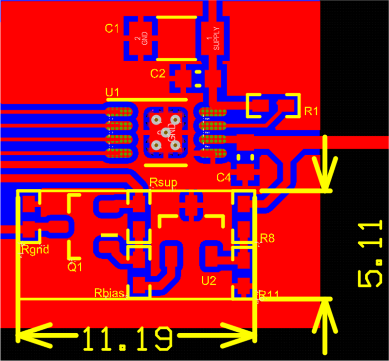
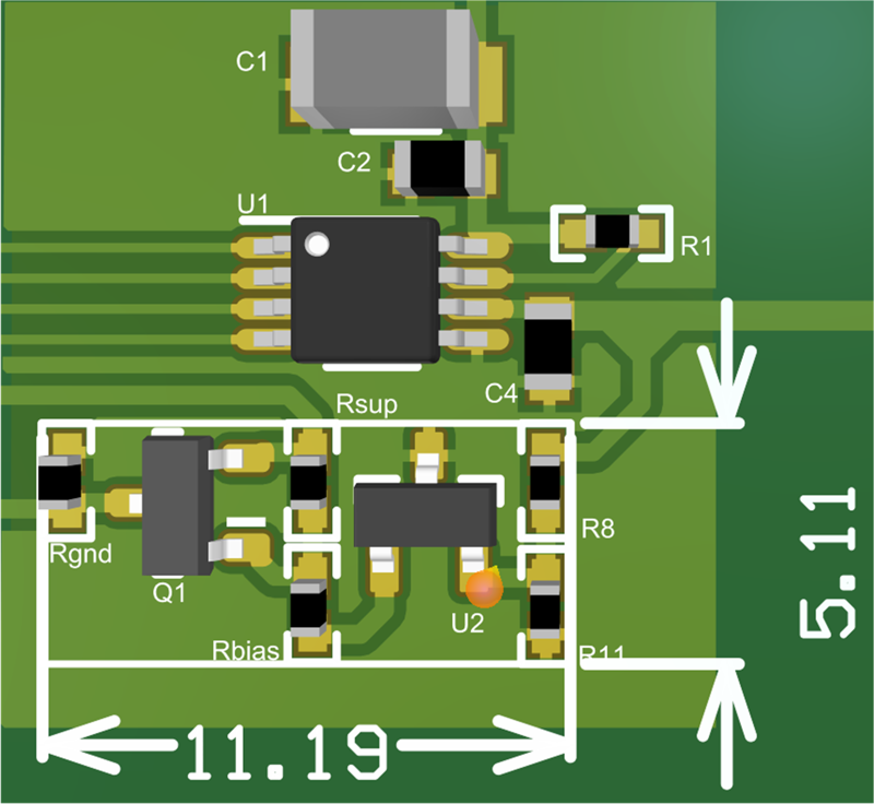
Figure 3-4 illustrates the PCB layout in a 2D view and Figure 3-5 utilizes a 3D view.
 Figure 3-4 2D Fault Detection Circuit
Layout
 Figure 3-5 3D Fault Detection Circuit
Layout
Figure 3-5 3D Fault Detection Circuit
LayoutThe fault detection circuit was added in conjunction to the TPS92611-Q1 EVM and highlighted in silk screen on the layout. As shown in the layout, the footprint for the fault detection circuit is compact, only requiring an area of 11.19 mm × 5.11 mm (440.55 mil × 201.18 mil).