SLVAFE5 September 2022 TPS92610-Q1 , TPS92611-Q1 , TPS92612-Q1 , TPS92613-Q1
2.2 Open Load vs Short-to-Battery Detection
The main approach for detecting between open load (OL) and short to battery (SB) is to measure the output voltage when the device output is disabled as shown in Figure 2-1. To do this, a voltage divider is required on the output of the TPS9261x-Q1 to verify that the comparator input is within a reasonable range and is not damaged. Remember, this pulls the output low in an open-load condition. Therefore, when a SB has occurred, the output voltage equals the battery, but in an OL condition, the output is pulled to ground. This now creates a detectable logical difference between the SB and OL conditions when the TPS9261x-Q1 output is disabled as shown in Figure 2-2.
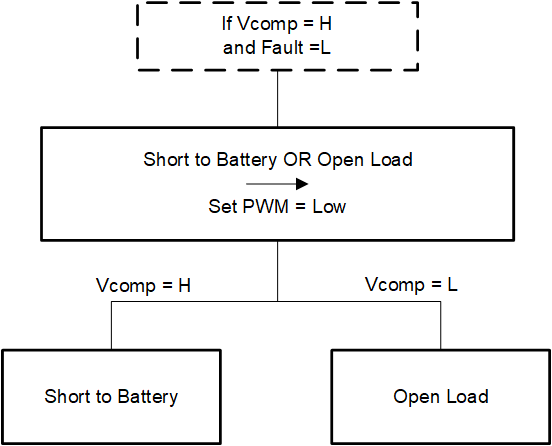
 Figure 2-2 Short to Battery (SB) or Open Load (OL) Logic Flowchart
If the fault pin is initially triggered and the comparator output Vcomp is HIGH, then a SB or OL has occurred. Thus, to differentiate between the two faults, the PWM pin must be pulled LOW. Then, if Vcomp stays HIGH a short to battery has occurred and if Vcomp is LOW an open load fault has occurred. However, if DIAGEN is pulled high, the device sources the 1-mA I(retry) current preventing the output from ever being disabled in either OL or SB conditions. Nevertheless, the I(retry) current can be compensated for by the voltage divider on the output. The resistor values can be selected so that when the 1-mA current is sourced by the LED driver, the voltage on the output is lower than the battery voltage during an OL condition. Now the comparator can be configured to compare the output voltage and the voltage expected during OL conditions when I(retry) is sourced through the resistive divider. Additionally, the fault pin is now released during an OL condition after the PWM pin is pulled low and the I(retry) current is sourced due to the output voltage dropping below battery voltage and causing the Vin – Vout to be greater than V(OPEN_th_rising) (OL, SB fault condition from Table 2-1). Figure 2-3 and Figure 2-4 show the SB and OL conditions with the 1-mA I(retry) when PWM is LOW.
Another method to avoid I(retry) completely is to disable the OL and SB fault detection by pulling the DIAGEN pin LOW. However, the device no longer pulls fault LOW in an OL or SB condition. This can be valid due to the comparator detecting this fault but when the DIAGEN pin is set HIGH the fault pin adds an additional level of robustness to the fault detection scheme.