SLVAET3 October   2021 TPS8802


  1.   Trademarks
  2. 1Introduction
  3. 2System Architecture
    1. 2.1 Battery Voltage
    2. 2.2 VCC Supply
      1. 2.2.1 Connecting VCC to VBST
      2. 2.2.2 Connecting VCC to VBAT Through a Switch
    3. 2.3 MCU Supply
      1. 2.3.1 MCU Connected to VBAT
      2. 2.3.2 MCU Connected to MCU LDO
      3. 2.3.3 MCU with VCC Connected to VBAT Through a Switch
    4. 2.4 Photoelectric Smoke Sensor LED Supply
      1. 2.4.1 LED Connected to VBAT
      2. 2.4.2 LED Connected to PLDO
      3. 2.4.3 LED Connected to LEDLDO
    5. 2.5 Example Schematics
      1. 2.5.1 Smoke and CO Schematics
      2. 2.5.2 Smoke-Only Schematics
  4. 3Current Consumption
    1. 3.1 Standby Current
      1. 3.1.1 TPS8802 Standby Current
      2. 3.1.2 Microcontroller Standby Current
    2. 3.2 Measurement Current
      1. 3.2.1 Smoke Measurement Current
      2. 3.2.2 CO Measurement Current
      3. 3.2.3 Battery Test Current
      4. 3.2.4 User Alarm Test Current
    3. 3.3 Other Current Consumption
      1. 3.3.1 Boost Charge Current
      2. 3.3.2 Initialization Current
  5. 4System Power Calculation and Measurements
    1. 4.1 Power Calculation Spreadsheet
      1. 4.1.1 Power Consumption Overview Page
      2. 4.1.2 Detailed Calculation Pages
    2. 4.2 Power Consumption Measurements
      1. 4.2.1 Power Measurement Method
      2. 4.2.2 Smoke and CO System Measurements
      3. 4.2.3 Smoke-Only System Measurements
  6. 5Summary
  7. 6References

LED Connected to PLDO

An infrared LED or low current blue LED can be powered through PLDO with a low-leakage Schottky diode. PLDO is supplied by VCC and can supply a voltage higher than VBAT if VCC is connected to VBST. PLDO has two operating modes: a pass-through mode when VCC is less than 5 V (typical), and a regulation mode when VCC is greater than 5 V (typical). The pass-through mode shorts PLDO to VCC. The regulation mode has a minimum 1 V drop between VCC and PLDO. Therefore, PLDO is most efficient when it is operating in the pass-through mode. The Schottky diode must be low-leakage, approximately 0.1 µA, to prevent the LED capacitor from discharging into PLDO when the boost converter is disabled. A silicon diode can be used instead of a Schottky diode if the higher voltage drop is tolerable.
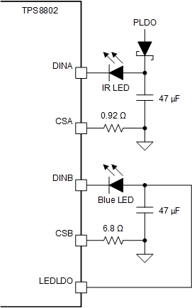
GUID-20200904-CA0I-4XXR-7MWZ-QJ4ZT3FG65JD-low.gif Figure 2-6 IR LED Connected to PLDO Through a Low-Leakage Schottky Diode