SLVAET3 October   2021 TPS8802


  1.   Trademarks
  2. 1Introduction
  3. 2System Architecture
    1. 2.1 Battery Voltage
    2. 2.2 VCC Supply
      1. 2.2.1 Connecting VCC to VBST
      2. 2.2.2 Connecting VCC to VBAT Through a Switch
    3. 2.3 MCU Supply
      1. 2.3.1 MCU Connected to VBAT
      2. 2.3.2 MCU Connected to MCU LDO
      3. 2.3.3 MCU with VCC Connected to VBAT Through a Switch
    4. 2.4 Photoelectric Smoke Sensor LED Supply
      1. 2.4.1 LED Connected to VBAT
      2. 2.4.2 LED Connected to PLDO
      3. 2.4.3 LED Connected to LEDLDO
    5. 2.5 Example Schematics
      1. 2.5.1 Smoke and CO Schematics
      2. 2.5.2 Smoke-Only Schematics
  4. 3Current Consumption
    1. 3.1 Standby Current
      1. 3.1.1 TPS8802 Standby Current
      2. 3.1.2 Microcontroller Standby Current
    2. 3.2 Measurement Current
      1. 3.2.1 Smoke Measurement Current
      2. 3.2.2 CO Measurement Current
      3. 3.2.3 Battery Test Current
      4. 3.2.4 User Alarm Test Current
    3. 3.3 Other Current Consumption
      1. 3.3.1 Boost Charge Current
      2. 3.3.2 Initialization Current
  5. 4System Power Calculation and Measurements
    1. 4.1 Power Calculation Spreadsheet
      1. 4.1.1 Power Consumption Overview Page
      2. 4.1.2 Detailed Calculation Pages
    2. 4.2 Power Consumption Measurements
      1. 4.2.1 Power Measurement Method
      2. 4.2.2 Smoke and CO System Measurements
      3. 4.2.3 Smoke-Only System Measurements
  6. 5Summary
  7. 6References

Connecting VCC to VBST

When using the TPS8802 with a 3-V battery, the boost converter can be used to power the horn, use the battery test load, and power a blue LED. The TPS8802 automatically enables the boost converter on power-up when over 2.0 V is applied to VCC. Connecting VCC to VBST allows the boost converter to provide the minimum 2.6 V required on VCC with a battery voltage as low as 2.0 V. Connecting VCC to VBST increases the usable voltage range of the battery, improving the battery life. During operation, the TPS8802 VCCLOW_BST feature can be used to automatically enable the boost converter when the VCC voltage drops below 2.4 V and disable the boost converter when the VCC voltage is above 2.5 V. The VCCLOW_BST feature sustains the VCC voltage above 2.4 V with low power consumption. The functional performance is unaffected when the VCC voltage is between 2.4 V and 2.6 V, although parametric performance may be affected.
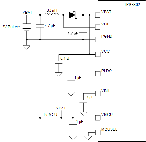
GUID-20200904-CA0I-H02Z-K41P-PNW60SVW8JHH-low.gif Figure 2-1 TPS8802 Power Connections with VCC Connected to VBST