SLVAET3 October   2021 TPS8802


  1.   Trademarks
  2. 1Introduction
  3. 2System Architecture
    1. 2.1 Battery Voltage
    2. 2.2 VCC Supply
      1. 2.2.1 Connecting VCC to VBST
      2. 2.2.2 Connecting VCC to VBAT Through a Switch
    3. 2.3 MCU Supply
      1. 2.3.1 MCU Connected to VBAT
      2. 2.3.2 MCU Connected to MCU LDO
      3. 2.3.3 MCU with VCC Connected to VBAT Through a Switch
    4. 2.4 Photoelectric Smoke Sensor LED Supply
      1. 2.4.1 LED Connected to VBAT
      2. 2.4.2 LED Connected to PLDO
      3. 2.4.3 LED Connected to LEDLDO
    5. 2.5 Example Schematics
      1. 2.5.1 Smoke and CO Schematics
      2. 2.5.2 Smoke-Only Schematics
  4. 3Current Consumption
    1. 3.1 Standby Current
      1. 3.1.1 TPS8802 Standby Current
      2. 3.1.2 Microcontroller Standby Current
    2. 3.2 Measurement Current
      1. 3.2.1 Smoke Measurement Current
      2. 3.2.2 CO Measurement Current
      3. 3.2.3 Battery Test Current
      4. 3.2.4 User Alarm Test Current
    3. 3.3 Other Current Consumption
      1. 3.3.1 Boost Charge Current
      2. 3.3.2 Initialization Current
  5. 4System Power Calculation and Measurements
    1. 4.1 Power Calculation Spreadsheet
      1. 4.1.1 Power Consumption Overview Page
      2. 4.1.2 Detailed Calculation Pages
    2. 4.2 Power Consumption Measurements
      1. 4.2.1 Power Measurement Method
      2. 4.2.2 Smoke and CO System Measurements
      3. 4.2.3 Smoke-Only System Measurements
  6. 5Summary
  7. 6References

Battery Test Current

The high current draw required for the battery test can make it a significant contributor to total power consumption. The average test load current is calculated in Equation 5, where IBATTEST is the battery test load current, TBATTEST is the battery test duration, and fBATTEST is the battery test frequency.

Equation 5. GUID-20200908-CA0I-207Q-NJKX-FRVC2PPR1GBK-low.gif

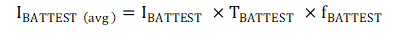
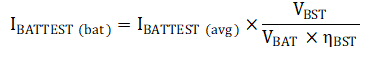
When using the TPS8802 battery test load, the load current is scaled by the boost input-output voltage ratio and efficiency. The average battery current draw caused by the battery test load is calculated in Equation 6.

Equation 6. GUID-20200908-CA0I-7JR9-GX9D-ZC2CLTGCQVKW-low.gif