SLVAET3 October   2021 TPS8802


  1.   Trademarks
  2. 1Introduction
  3. 2System Architecture
    1. 2.1 Battery Voltage
    2. 2.2 VCC Supply
      1. 2.2.1 Connecting VCC to VBST
      2. 2.2.2 Connecting VCC to VBAT Through a Switch
    3. 2.3 MCU Supply
      1. 2.3.1 MCU Connected to VBAT
      2. 2.3.2 MCU Connected to MCU LDO
      3. 2.3.3 MCU with VCC Connected to VBAT Through a Switch
    4. 2.4 Photoelectric Smoke Sensor LED Supply
      1. 2.4.1 LED Connected to VBAT
      2. 2.4.2 LED Connected to PLDO
      3. 2.4.3 LED Connected to LEDLDO
    5. 2.5 Example Schematics
      1. 2.5.1 Smoke and CO Schematics
      2. 2.5.2 Smoke-Only Schematics
  4. 3Current Consumption
    1. 3.1 Standby Current
      1. 3.1.1 TPS8802 Standby Current
      2. 3.1.2 Microcontroller Standby Current
    2. 3.2 Measurement Current
      1. 3.2.1 Smoke Measurement Current
      2. 3.2.2 CO Measurement Current
      3. 3.2.3 Battery Test Current
      4. 3.2.4 User Alarm Test Current
    3. 3.3 Other Current Consumption
      1. 3.3.1 Boost Charge Current
      2. 3.3.2 Initialization Current
  5. 4System Power Calculation and Measurements
    1. 4.1 Power Calculation Spreadsheet
      1. 4.1.1 Power Consumption Overview Page
      2. 4.1.2 Detailed Calculation Pages
    2. 4.2 Power Consumption Measurements
      1. 4.2.1 Power Measurement Method
      2. 4.2.2 Smoke and CO System Measurements
      3. 4.2.3 Smoke-Only System Measurements
  6. 5Summary
  7. 6References

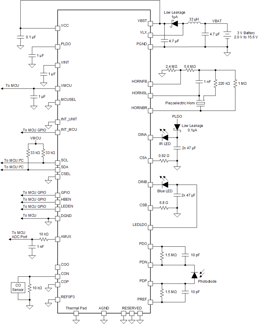
Smoke and CO Schematics

GUID-20200904-CA0I-ZQJL-TM4P-0HBMP878QKFS-low.gif Figure 2-7 Smoke and CO System Schematics for Minimum Power Consumption

The smoke and CO system connects VBST to VCC to allow battery voltages down to 2.0 V. Here the MCU LDO is set to 1.8 V, a low voltage that can be powered without the boost converter being enabled. The boost converter can be enabled to 2.7 V, 3.8 V, or 4.7 V to supply the IR LED through PLDO with a low-leakage (0.1 µA) Schottky diode. The blue LED is supplied by the LED LDO to support the higher blue LED forward voltage. The CO amplifier is continuously enabled to track the slowly-varying CO concentration signal.