SLVA927A November 2017 – April 2019 LM25066A , LM25066I , LM5050-1 , LM5051 , LM5064 , LM5066 , LM5067 , LM5069 , LM66100 , LM74500-Q1 , LM74700-Q1 , TPL7407LA , TPS1H100-Q1 , TPS1HA08-Q1 , TPS2113A , TPS2115A , TPS22810 , TPS22915 , TPS22916 , TPS22918 , TPS22971 , TPS22990 , TPS23525 , TPS2412 , TPS24751 , TPS24770 , TPS25942A , TPS2595 , TPS2660 , TPS27S100 , TPS2H160-Q1 , TPS4H160-Q1 , ULN2003A
5 Ideal Diode, ORing Controllers
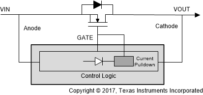
 Figure 6. Ideal Diode Block Diagram
 Ideal diode controllers control an external FET and, similar to a regular diode, can block reverse current whenever a reverse voltage event occurs. Whenever one of these events occur, the controller shuts off the FET and uses the body diode to prevent any transients from damaging upstream components. The controller can also prevent against ground shorts at the input (VIN) by using the same method.
Ideal diode controllers can also protect against reverse polarity conditions, commonly caused by connecting a battery incorrectly or mis-wiring a power supply. If you accidentally switch the polarity on VIN, an additional diode from the controller to GND can be included to prevent damage to the IC or the power source. The controller also significantly lowers power dissipation normally found across diodes. By driving the external FET instead of a diode, the voltage drop typically found across diode solutions can be minimized.
Ideal diodes can also act as ORing controllers. Basic power redundancy architecture contains two or more power supplies connected to a single load. ORing solutions allow the system to switch between power sources if one were to fail, and can even connect power sources in parallel. This allows for uninterrupted power and saves on redundant power supply costs.
Table 6. Ideal Diode Controller Examples (1)
| DESCRIPTION | DEVICE | RECOMMENDED VOLTAGE RANGE | TYPICAL QUIESCENT CURRENT | FORWARD VOLTAGE THRESHOLD | PACKAGE |
|---|---|---|---|---|---|
| Fast turnoff, voltage sensing | TPS241x | 3 V to 16.5 V | N/A | 10 mV | SOP and SOIC |
| Automotive qualified, low Iq, high efficiency | LM74700-Q1 | 3.2 V to 65 V | 80 µA | 20 mV | SOT |
| Low side ORing controller, FET diagnostics | LM5051 | –6 V to –100 V | 69 µA | 45 mV | SOIC |
| Low Iq, reverse current protection, integrated FET | LM66100 | 1.5 V to 5.5 V | 0.2 µA | 79 mV (2) | SC-70 |