SLAU821 October 2019
3.3 Power Supply
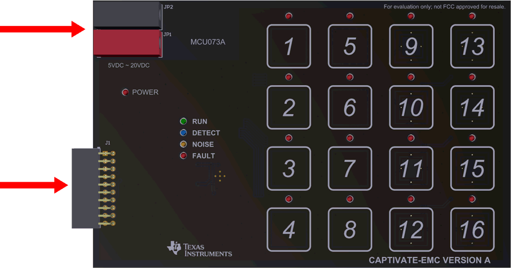
There are two power supply options for CAPTIVATE-EMC board (see Figure 4):
- 5 V to 20 V DC power through connectors JP1 and JP2. The color of the connectors shows the polarity, red for positive and black for negative. A TI TPS7A4533 +3.3-V 1.5-A LDO provides power for all the devices on the CAPTIVATE-EMC.
- The CAPTIVATE-PGMR board also can provide 3.3-V power supply to the CAPTIVATE-EMC through connector J1.
 Figure 4. CAPTIVATE-EMC Power Supply Options
 NOTE
Do not connect the CAPTIVATE-PGMR directly to the CAPTIVATE-EMC when a DC power supply is enabled.