SLAA898 September 2022 TAS3251 , TPA3255
3.3 System Test
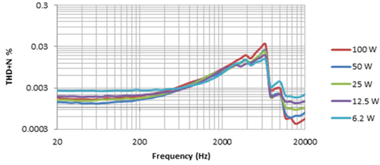
- Make sure the TPA3255 device is set up and working properly. Connect a 4-Ω resistor using amplifier configuration in BTL mode (without any transformers), and sweep frequency under different power levels.
 Figure 3-6 THD+N vs Frequency Results Based on TPA3255 Without Transformer
 - As Figure 3-7 shows, build the constant voltage system using one step-up and one step-down
transformer (simplify the system by applying one load to start) with a 4-Ω
resistor connected to 4-Ω tap of the secondary side of the 330-040. Apply a
1-kHz signal and modify the input amplitude until RMS (root mean square) of U
reaches 70.7 V (peak to peak is about 200 V). Note:
Since the voltage is very high, necessary protection methods must be taken.
For the 330-040, set 10 W, 5 W, 2.5 W, 1.25 W, and 0.62 W (all 70 V) respectively, and use an Audio Precision (AP) analyzer to measure voltage and power across resistor R0. Make sure the output voltage and power are as expected.
 Figure 3-7 Simplified Constant
Voltage System
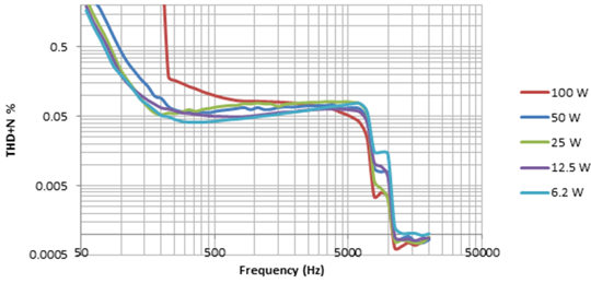
 - Assemble the complete constant voltage system based on Figure 3-5 using 10 step-down transformers (N = 10) and 10 × 4-Ω resistors. Set the input to 70.7 VRMS. Start by using the 0.62-W power level for each 330-040, and measure the THD+N vs frequency as shown in Figure 3-8. Multiply the power measured on one resistor by 10 to calculate the total efficient power. Do the same thing for the 1.25-, 2.5-, 5-, and 10-W settings.
 Figure 3-8 THD+N Versus Frequency Results Based on TPA3255 With 1 Step-Up and 10 Step-Down Transformers (1, 2 as Primary Side and A, B as Secondary Side)
Table 3-7 shows the power consumed and relevant efficiency when using the 330-040 with a 10-W configuration.
Table 3-7 System Efficiency for Ten 10-W Resistor Loads (Using One
Peavey® 18737 and Ten 330-040 Transformers)
| Power Level | Total Power (W) | Power for Each Resistor | Total Efficient Power (W) | Efficiency |
|---|---|---|---|---|
| 10 W | 186.66 | 9.737 | 97.37 | 0.522 |