SLAA898 September   2022 TAS3251 , TPA3255


  1.   Abstract
  2.   Trademarks
  3. 1Introduction
    1. 1.1 Power Amplifiers
    2. 1.2 Discrete Power Amplifier Implementation
    3. 1.3 Class-D Amplifier Implementation
    4. 1.4 Advantage of a Class-D Implementation
  4. 2Background
    1. 2.1 Why Use Constant Voltage Audio Systems
    2. 2.2 Basic Principle of Constant Voltage Systems
    3. 2.3 Power Loss in Transformer
    4. 2.4 Auto-Transformer
  5. 3System Test (Based on TPA3255)
    1. 3.1 Transformer Characteristics
      1. 3.1.1 Turns Ratio and Resistance Match
      2. 3.1.2 DCR of the Transformer
    2. 3.2 System Build-Up
    3. 3.3 System Test
  6. 4Efficiency Analysis and Optimization
    1. 4.1 Efficiency of Three Parts
      1. 4.1.1 Efficiency for TPA3255
      2. 4.1.2 Efficiency for Step-Up Transformer
      3. 4.1.3 Efficiency for Step-Down Transformer 330-040
    2. 4.2 Improvements on System Efficiency
      1. 4.2.1 Improve Resistance Matching
      2. 4.2.2 Apply a Transformer With Less Power Loss
  7. 5Considerations on Building a Constant Voltage System
    1. 5.1 Transformer Saturation
    2. 5.2 Low DCR
    3. 5.3 Resistance Matching

Efficiency for Step-Down Transformer 330-040

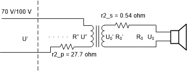
GUID-7D2311AF-B4E9-43D5-A1A2-30C653CC13AE-low.gif Figure 4-2 Equivalent System Circuit Including DCR for Peavey® 330-040

Since the amplifier cannot generate a 70-VRMS signal to the 330-040, it is not easy to test the efficiency through experiment. According to Table 3-6, the DCR is relatively large for the step-down transformer. If only taking copper loss into consideration,

Equation 18. P 0 = U 0 2 R 0
Equation 19. U 0 = R 0 R 0 + r 2 _s U 0 '
Equation 20. R " = ( U " U 0 ' ) 2 ( R 0 + r 2 _s )
Equation 21. U " = R " R " + r 2 _p U '

For the step down transformer:

Equation 22. η down = R " ( R " + r 2 _p ) R 0 ( R 0 + r 2 _s )

According to Table 3-3 (configure 10 W as primary and 4 Ω as secondary):

Equation 23. R " = 124 . 97 × ( 4 + 0 . 54 ) = 567 . 36   Ω
Equation 24. η d o w n = 567 . 36 ( 567 . 36 + 27 . 7 ) 4 ( 4 + 0 . 54 = 0 . 84

As in the previous experiment, when using ten 4-Ω resistors configured as 10 W in Figure 3-5, the efficiency of the TPA3255 ηamp and step-up transformer ηup 18737 is 0.8 and 0.9 respectively (see Figure 4-1), so the system efficiency is about:

Equation 25. η = η amp n up η down = 0 . 8 × 0 . 9 × 0 . 84 = 0 . 605

This is 0.08 higher than the test result because, in one case, the iron loss in the step-down transformer is not considered here. Conversely, as power goes up, the current in the transformer gets higher and higher, which reduces the turns ratio and equivalent resistance as a result. This makes the amplifier load below 4 Ω, and thus reduces the efficiency of the TPA3255 device to below 0.8.