SLAA898 September   2022 TAS3251 , TPA3255


  1.   Abstract
  2.   Trademarks
  3. 1Introduction
    1. 1.1 Power Amplifiers
    2. 1.2 Discrete Power Amplifier Implementation
    3. 1.3 Class-D Amplifier Implementation
    4. 1.4 Advantage of a Class-D Implementation
  4. 2Background
    1. 2.1 Why Use Constant Voltage Audio Systems
    2. 2.2 Basic Principle of Constant Voltage Systems
    3. 2.3 Power Loss in Transformer
    4. 2.4 Auto-Transformer
  5. 3System Test (Based on TPA3255)
    1. 3.1 Transformer Characteristics
      1. 3.1.1 Turns Ratio and Resistance Match
      2. 3.1.2 DCR of the Transformer
    2. 3.2 System Build-Up
    3. 3.3 System Test
  6. 4Efficiency Analysis and Optimization
    1. 4.1 Efficiency of Three Parts
      1. 4.1.1 Efficiency for TPA3255
      2. 4.1.2 Efficiency for Step-Up Transformer
      3. 4.1.3 Efficiency for Step-Down Transformer 330-040
    2. 4.2 Improvements on System Efficiency
      1. 4.2.1 Improve Resistance Matching
      2. 4.2.2 Apply a Transformer With Less Power Loss
  7. 5Considerations on Building a Constant Voltage System
    1. 5.1 Transformer Saturation
    2. 5.2 Low DCR
    3. 5.3 Resistance Matching

Improve Resistance Matching

One cause of the low system efficiency is the low equivalent resistance seen by the amplifier. The equivalent load can be increased by reconfiguring the 18737. From Table 3-1, RL can be about 8 Ω if using tap 1, 3 as primary and tap A, B as secondary (or tap 4 as primary and tap C as secondary). With an 8-Ω load, ηamp increases from 0.8 to about 0.85. The theoretical system efficiency is:

Equation 26. η=ηampηupηdown=0.85×0.9×0.84=0.64

The final test result is about 0.61, which matches with the estimation. Figure 4-3 shows the THD+N test result with new configuration.
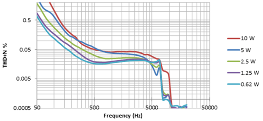
GUID-D64D87BD-4629-4C03-B5B1-C31E8AB4B2AF-low.pngFigure 4-3 THD+N vs Frequency Results Based on TPA3255 With One Peavey® Step-up Transformer and 10 Step-Down Transformers (1, 3 as Primary Side and A, B as Secondary Side)