SLAA898 September 2022 TAS3251 , TPA3255
3.1.1 Turns Ratio and Resistance Match
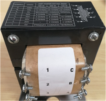
See the data sheet for turns ratio when using different configurations. For the transformer in Figure 3-1, the voltage on the primary and secondary sides has been marked. The turns ratio (abbreviated as TR) is proportional with the voltage ratio. Table 3-1 show the basic characteristics of the transformer.
 Figure 3-1 Step-Up Transformer From
Peavey® (Auto Match II 400W 18737)
Figure 3-1 Step-Up Transformer From
Peavey® (Auto Match II 400W 18737)| Configuration | Parameters | Secondary: Tap A, B (70.7 V) | Secondary: Tap A, C (100 V) |
|---|---|---|---|
| Primary: tap 1, 2 (20 V) | TR | 1/3.535 | 1/5 |
| U1/U2 | 1/3.535 | 1/5 | |
| R1/R2 | 1/12.496225 | 1/25 | |
| Primary: tap 1, 3 (28 V) | TR | 1/2.525 | 1/3.571 |
| U1/U2 | 1/2.525 | 1/3.571 | |
| R1/R2 | 1/6.375625 | 1/12.752041 | |
| Primary: tap 1, 4 (40 V) | TR | 1/1.7675 | 1/2.5 |
| U1/U2 | 1/1.7675 | 1/2.5 | |
| R1/R2 | 1/3.124056 | 1/6.25 | |
| Primary: tap 1, 5 (56 V) | TR | 1/1.2625 | 1/1.786 |
| U1/U2 | 1/1.2625 | 1/1.786 | |
| R1/R2 | 1/1.593906 | 1/3.189796 |
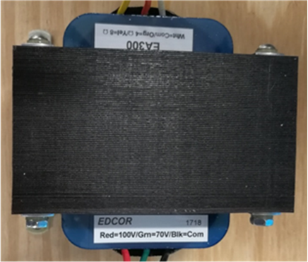
For the transformer in Figure 3-2, the voltage level is not marked on one side (4 Ω, 8 Ω side). Two methods can be applied to determine the turns ratio. First, a 300-W transformer. If 4 Ω is the primary configuration, and 300 W must be reached when the input is about 34.6 V (according to Equation 2), the turns ratio can be calculated as 34.6 / 70.7 = 1 / 2.04 under 4 Ω, 70 V configuration. If 8 Ω is the primary configuration, the corresponding voltage level is about 49 V, and the turns ratio for 8 Ω, 70 V is 49 / 70.7 = 1 / 1.44. The other option is to connect a certain resistor (say 40 Ω) to one side and test the equivalent resistance on the other side. If connecting 16 Ω to tap 70 V, and measuring the resistance between tap "4 Ω" and tap “Com” is measured as 3.84 Ω, the relevant turns ratio is 2.04 according to Equation 1.
 Figure 3-2 Step-Up Transformer From
EDCOR® (EA300)
Figure 3-2 Step-Up Transformer From
EDCOR® (EA300)| Configuration | Parameters | Secondary: 70.7 V | Secondary: 100 V |
|---|---|---|---|
| Primary 4 Ω | TR | 1/2.04 | 1/2.89 |
| U1/U2 | 1/2.04 | 1/2.89 | |
| R1/R2 | 1/4.1616 | 1/8.3521 | |
| Primary: 8 Ω | TR | 1/1.45 | 1/2.05 |
| U1/U2 | 1/1.45 | 1/2.05 | |
| R1/R2 | 1/2.1025 | 1/4.2025 |
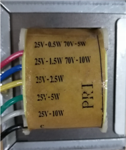
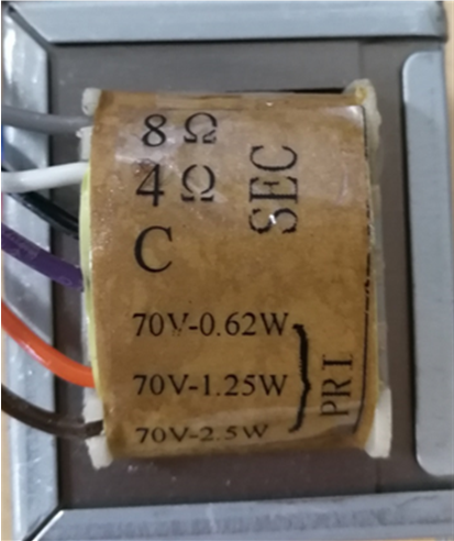
For the step-down transformer in Figure 3-3, the turns ratio can be determined by measuring the equivalent resistance. In this case, a 70-V system was considered. For the primary side, the voltage and power is known. And for secondary side, the reference resistive load is known. Suppose input power P (10 W, 5 W, 2.5 W, 1.25 W or 0.62 W), primary voltage U1 (70.7 V), equivalent resistance, R1, and secondary side voltage is U2 (unknown), or R2 (4 Ω or 8 Ω). If power losses are ignored, the power on both sides should be the same.
The turns ratio was determined using Equation 10.
 Figure 3-3 Step-Down Transformer From
Peavey® (330-040) (a)
 Figure 3-4 Step-Down Transformer From
Peavey® (330-040) (b)
Figure 3-4 Step-Down Transformer From
Peavey® (330-040) (b)| Configuration | Parameters | Secondary: 4 Ω | Secondary: 8 Ω |
|---|---|---|---|
| Primary: 10 W | TR | 11.179 | 7.905 |
| U1/U2 | 11.179 | 7.905 | |
| R1/R2 | 124.9700 | 62.4890 | |
| Primary: 5 W | TR | 15.809 | 11.179 |
| U1/U2 | 15.809 | 11.179 | |
| R1/R2 | 249.9245 | 124.9700 | |
| Primary: 2.5 W | TR | 22.357 | 15.809 |
| U1/U2 | 22.357 | 15.809 | |
| R1/R2 | 499.8354 | 249.9245 | |
| Primary 1.25 W | TR | 31.618 | 22.357 |
| U1/U2 | 31.618 | 22.357 | |
| R1/R2 | 999.6979 | 499.8354 | |
| Primary 0.62 W | TR | 44.895 | 31.745 |
| U1/U2 | 44.895 | 31.745 | |
| R1/R2 | 2015.5610 | 1007.7450 |