SLAA475A October 2010 – March 2019 MSP430L092
-
MSP430x09x Analog Pool: Feature Set and Advanced Use
- Trademarks
- 1 MSP430x09x Overview
- 2
Analog Pool (A-Pool)
- 2.1 Input Dividers
- 2.2 Internal Reference
- 2.3 Starting and Stopping the A-Pool
- 2.4 Comparator Function
- 2.5 8-Bit DAC Function
- 2.6 8-Bit ADC Function
- 2.7 SVM Function
- 2.8 Use of Multiple Features
- 2.9 Temperature Measurements With the A-Pool
- 2.10 Fractional and Integer Number Use
- 2.11 APINTB and APFRACTB Use With ATBU and EOCBU
- 2.12 A-Pool Trigger Sources
- 2.13 Filtering ADC Conversions With Digital Filters
- 3 Summary
- 4 References
- Revision History
2.5 8-Bit DAC Function
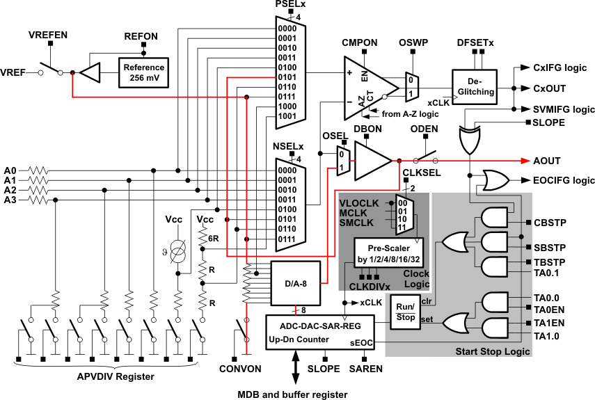
Within the MSP430x09x, an 8-bit DAC is implemented to generate voltages between 0 and 256 mV. The reference voltage for the DAC is the 256 mV generated internally from the reference module. The DAC voltage either can be used internally as an input for the comparator selected with the multiplexers or can be switched out on the AOUT pin. To set a voltage, the APINT register must be filled with the correct value, and the output buffer select (OSEL) and DAC buffer enable signal (DBON) bits must be set. To output the analog voltage on the port pin, it is necessary also to set the output driver (ODEN) bit. Any change of the APINT value is directly visible on the generated analog voltage.
A simple DAC code example follows. On the AOUT pin, a rising wave can be observed. Figure 4 shows the used paths through the A-Pool.
#include "msp430l092.h"
void main( void )
{
  // Stop watchdog timer to prevent time out reset
  WDTCTL = WDTPW + WDTHOLD;
  APCNF = DBON+CONVON+APREFON;       // Enable DAC buffer +
                                     // Enable conversion +
                                     // Enable reference
  APCTL = ODEN+OSEL;                 // Set DAC output to pin +
                                     // Select output buffer
  while (1)
  {
    APINT = APINT + 1;               // Increment APINT value
  }
}
 Figure 4. Example of DAC Function