SLAA202B February 2005 – December 2018 MSP430F149 , MSP430F149 , MSP430F2252-Q1 , MSP430F2252-Q1 , MSP430F2272-Q1 , MSP430F2272-Q1 , MSP430F2274 , MSP430F2274 , MSP430FG4619 , MSP430FG4619
-
Implementing IrDA With MSP430™ MCUs
- Trademarks
- 1 Introduction
- 2 Hardware Description
- 3 Software Description
- 4 PC Demonstration Application
- 5 IrDA Protocol Basics
- 6 IrDA Communication Diagram
- 7 Frame Exchange Log
- 8 References
- Revision History
5.2 Link Access Protocol (IrLAP) Layer
The link access protocol (IrLAP) layer is responsible for reliable data transfer at a low level; upper layers can then rely on the services provided by this layer. The data is delivered and if delivery is not possible, then the upper layer is aware of this fact and acts accordingly. The IrLAP layer provides a point-to-point half-duplex connection with no data collision control mechanism. It is possible to simulate a full-duplex connection when the timing requirements are not critical.
The devices connected to the IrLAP layer are known as the primary and secondary devices which correspond to a master-slave relationship, respectively. The responsibilities of each device vary depending on the role it performs. Although many times a primary station can take on the role of a secondary, the opposite is not true when a secondary-only implementation is followed.
The primary station is responsible for:
- Sending command frames (commencing connections and transfers)
- Control and organization of data
- Manipulating data link errors
The secondary station:
- Sends response frames only
The IrLAP layer is built around two modes of operations: normal disconnect mode (NDM) and normal response mode (NRM). NDM is used when a connection does not yet exist. When the devices identify the IR media to be free, then the discovery process can begin with the default parameters for negotiating a connection. NRM is used when a connection exists and then upper layers proceed to exchange information. Figure 17 shows the basic IrLAP frame format.
 Figure 17. IrLAP Frame Format
 The address and control fields only take 1 byte each; thus, adding little overhead to user data. Three different framings exist that are applied to the data before it is sent. Proper framing depends solely on the speed at which the data is sent. The scope of this report is up to 115.2 kbps; therefore, asynchronous framings schemes are followed.
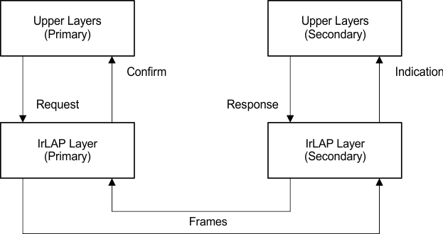
The operations performed by this layer are defined in its service primitives; these can be understood as IrLAP API definitions. Figure 18 shows an example of how these service primitives work. Not all the primitives defined are required to have an IrDA implementation. The primitives defined by the IrDA Lite protocol as required are:
- Discovery and address conflict services
- Connect services
- Data services
- Disconnect services
 Figure 18. IrLAP Service Primitives