SLAA202B February 2005 – December 2018 MSP430F149 , MSP430F149 , MSP430F2252-Q1 , MSP430F2252-Q1 , MSP430F2272-Q1 , MSP430F2272-Q1 , MSP430F2274 , MSP430F2274 , MSP430FG4619 , MSP430FG4619
-
Implementing IrDA With MSP430™ MCUs
- Trademarks
- 1 Introduction
- 2 Hardware Description
- 3 Software Description
- 4 PC Demonstration Application
- 5 IrDA Protocol Basics
- 6 IrDA Communication Diagram
- 7 Frame Exchange Log
- 8 References
- Revision History
3.3.3 Data Services
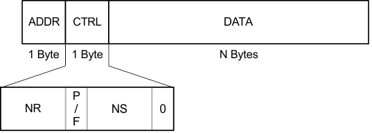
After a connection has been established, a change occurs from NDM to NRM. Once in NRM mode, higher layers take over the connection, and IrLAP frames are used as a means to transfer their data reliably. All the frames exchanged must follow the IrLAP information (I) format. The main feature of this frame format is the inclusion of the Nr, Ns, and Poll/Final (P/F) bits as seen in Figure 10.
 Figure 10. Information Frame Format
 First, the connection address is verified to ensure that a reply to a frame that was not meant for the MSP430 is ignored. If the connection address was the one assigned to the MSP430, then the frame sequence is verified through the comparison of the value stored in Nr and the value of Ns in the incoming frame. If this check is successful, then the value stored in Nr is now incremented by 1, and the frame is passed to the upper layers for proper manipulation. If the check is unsuccessful, then the frame is ignored, and the connection is dropped. The other condition while in NRM that could cause the connection to be dropped from the IrLAP layer, not including a disconnect request, is if an SNRM frame is received, in which case a request disconnect (RD) response is issued to the primary.
If data is requested by an upper layer while in NRM, then data is queued and buffered, the parts of the frame corresponding to IrLAP are prepared, and the frame is the responsibility of the higher layer. If an I-command frame is received, then it means that the secondary stack is now allowed to transmit frames. Depending on the state of the Ns and Nr counts, either an I- response frame carrying data or an S-response of the type receive ready (RR) or receive not ready (RNR) is sent. The response to receiving a RR command frame is similar to the one explained above as are the responses to RNR and reject (REJ) commands. The same response is also issued in the case of an unknown command frame with the P bit set and from an unknown type frame as it is described in the IrLAP state table for IrDA Lite.
On the other hand, if a U-frame carrying a disconnect command is received, then the proper UA response is issued and the connection state is now NDM.