SBOU278 December   2021


  1.   Trademarks
  2. 1Overview
    1. 1.1 OPT4001YMNEVM Kit Contents
    2. 1.2 Related Documentation from Texas Instruments
  3. 2OPT4001YMNEVM Hardware
    1. 2.1 Theory of Operation for the OPT4001YMNEVM
    2. 2.2 OPT4001YMNEVM Hardware Overview
  4. 3OPT4001YMNEVM Software
    1. 3.1 Hardware Requirements
    2. 3.2 Software Installation
    3. 3.3 Typical OPT4001YMNEVM Hardware Setup
    4. 3.4 Launching the OPT4001EVM Software
    5. 3.5 OPT4001EVM Software Operation
      1. 3.5.1 Getting Started
      2. 3.5.2 Feature Descriptions
  5. 4Schematic, PCB Layout, and Bill of Materials
    1. 4.1 Flex Coupon Board
      1. 4.1.1 Schematic
      2. 4.1.2 PCB Layout
      3. 4.1.3 Bill of Materials
    2. 4.2 Rigid Coupon Board
      1. 4.2.1 Schematic
      2. 4.2.2 PCB Layout
      3. 4.2.3 Bill of Materials
    3. 4.3 Motherboard
      1. 4.3.1 Schematic
      2. 4.3.2 PCB Layout
      3. 4.3.3 Bill of Materials
  6. 5Troubleshooting
    1. 5.1 Microsoft Windows 7 Manual Driver Installation

OPT4001YMNEVM Hardware

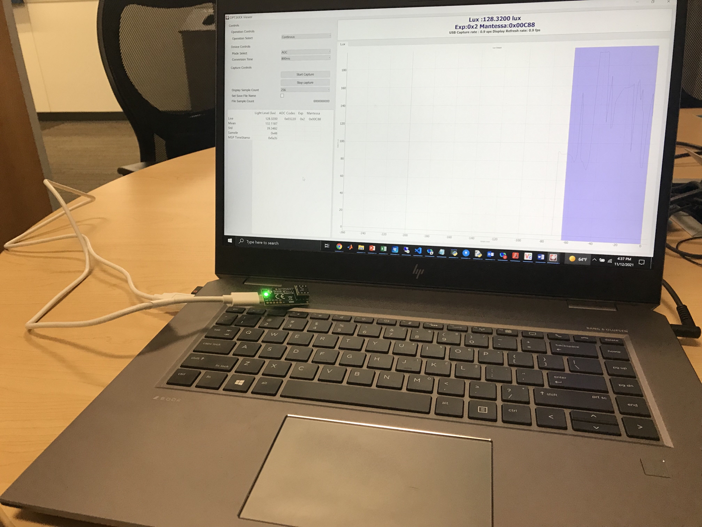
Figure 2-1 shows the system setup for the OPT4001YMNEVM. The computer runs the graphical user interface (GUI) software that communicates with the OPTMBEVM board over a USB connection. The OPTMBEVM has a USB Type C port and ships with a USB-C to USB-A cable. The OPTMBEVM board acts as a bridge between the software running on the PC and the OPT4001YMN coupon board. The MSP430 on the OPTMBEVM receives USB commands from the PC and communicates with the OPT4001YMN over I2C.
GUID-8DAAF95E-F8E1-4733-AD41-C56A92FC0EFD-low.jpgFigure 2-1 EVM Hardware Setup