SBOU278 December   2021


  1.   Trademarks
  2. 1Overview
    1. 1.1 OPT4001YMNEVM Kit Contents
    2. 1.2 Related Documentation from Texas Instruments
  3. 2OPT4001YMNEVM Hardware
    1. 2.1 Theory of Operation for the OPT4001YMNEVM
    2. 2.2 OPT4001YMNEVM Hardware Overview
  4. 3OPT4001YMNEVM Software
    1. 3.1 Hardware Requirements
    2. 3.2 Software Installation
    3. 3.3 Typical OPT4001YMNEVM Hardware Setup
    4. 3.4 Launching the OPT4001EVM Software
    5. 3.5 OPT4001EVM Software Operation
      1. 3.5.1 Getting Started
      2. 3.5.2 Feature Descriptions
  5. 4Schematic, PCB Layout, and Bill of Materials
    1. 4.1 Flex Coupon Board
      1. 4.1.1 Schematic
      2. 4.1.2 PCB Layout
      3. 4.1.3 Bill of Materials
    2. 4.2 Rigid Coupon Board
      1. 4.2.1 Schematic
      2. 4.2.2 PCB Layout
      3. 4.2.3 Bill of Materials
    3. 4.3 Motherboard
      1. 4.3.1 Schematic
      2. 4.3.2 PCB Layout
      3. 4.3.3 Bill of Materials
  6. 5Troubleshooting
    1. 5.1 Microsoft Windows 7 Manual Driver Installation

Typical OPT4001YMNEVM Hardware Setup

Plug the male USB-C cable to the OPTMBEVM board and then plug the male USB-A cable into the computer. The green light will light up on the EVM as shown in Figure 3-9.
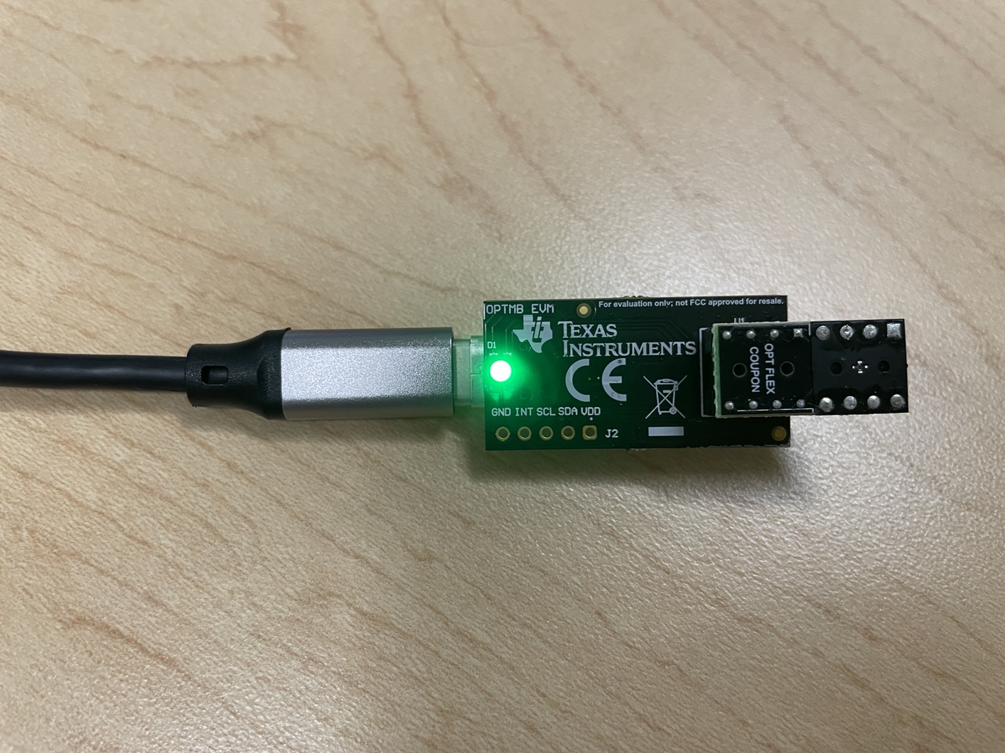
GUID-20211220-SS0I-9KDC-JQ9R-M8SSC6JJWRB6-low.jpg Figure 3-9 Typical Hardware Connection

When the EVM is plugged into the USB port of the computer it will enumerate as two com ports. This will show up in the Windows device manager as show in Figure 3-10.

GUID-20211220-SS0I-FRDV-V74T-1LQDFL11V5ZJ-low.png Figure 3-10 Typical Response After Connecting OPT4001YMNEVM to the Computer

Connect the EVM via USB to the PC. If Windows shows a notification that a driver is not found for the device connected, see the instructions to manually install drivers in Section 5.1 before proceeding.