ZHCS181G August 2011 – April 2021 TPS53355
PRODUCTION DATA
- 1 特性
- 2 应用
- 3 说明
- 4 Revision History
- 5 Pin Configuration and Functions
- 6 Specifications
-
7 Detailed Description
- 7.1 Overview
- 7.2 Functional Block Diagram
- 7.3
Feature Description
- 7.3.1 5-V LDO and VREG Start-Up
- 7.3.2 Adaptive On-Time D-CAP Control and Frequency Selection
- 7.3.3 Ramp Signal
- 7.3.4 Adaptive Zero Crossing
- 7.3.5 Power-Good
- 7.3.6 Current Sense, Overcurrent and Short Circuit Protection
- 7.3.7 Overvoltage and Undervoltage Protection
- 7.3.8 UVLO Protection
- 7.3.9 Thermal Shutdown
- 7.4 Device Functional Modes
- 8 Application and Implementation
- 9 Power Supply Recommendations
- 10Layout
- 11Device and Documentation Support
- 12Mechanical, Packaging, and Orderable Information
封装选项
请参考 PDF 数据表获取器件具体的封装图。
机械数据 (封装 | 引脚)
- DQP|22
散热焊盘机械数据 (封装 | 引脚)
- DQP|22
订购信息
7.3.6 Current Sense, Overcurrent and Short Circuit Protection
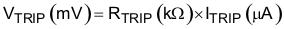
TPS53355 has cycle-by-cycle overcurrent limiting control. The inductor current is monitored during the OFF state and the controller maintains the OFF state during the period in that the inductor current is larger than the overcurrent trip level. In order to provide both good accuracy and cost effective solution, TPS53355 supports temperature compensated MOSFET RDS(on) sensing. The TRIP pin should be connected to GND through the trip voltage setting resistor, RTRIP. The TRIP terminal sources current (ITRIP) which is 10 μA typically at room temperature, and the trip level is set to the OCL trip voltage VTRIP as shown in Equation 1.
The inductor current is monitored by the LL pin. The GND pin is used as the positive current sensing node and the LL pin is used as the negative current sense node. The trip current, ITRIP has 4700ppm/°C temperature slope to compensate the temperature dependency of the RDS(on).
As the comparison is made during the OFF state, VTRIP sets the valley level of the inductor current. Thus, the load current at the overcurrent threshold, IOCP, can be calculated as shown in Equation 2.

In an overcurrent or short circuit condition, the current to the load exceeds the current to the output capacitor thus the output voltage tends to decrease. Eventually, it crosses the undervoltage protection threshold and shuts down. After a hiccup delay (16 ms with 0.7 ms sort-start), the controller restarts. If the overcurrent condition remains, the procedure is repeated and the device enters hiccup mode.
Hiccup time calculation:
where
- n = 8, 9, 10, or 11 depending on soft start time selection
| SELECTED SOFT-START TIME (tSS) (ms) | n | HICCUP WAIT TIME (tHIC(wait)) (ms) | HICCUP DELAY TIME (tHIC(dly)) (ms) |
|---|---|---|---|
| 0.7 | 8 | 2.052 | 14.364 |
| 1.4 | 9 | 3.076 | 21.532 |
| 2.8 | 10 | 5.124 | 35.868 |
| 5.6 | 11 | 9.220 | 64.540 |