ZHCS490B November 2011 – December 2018 TMP104
PRODUCTION DATA.
7.3.3 Global Initialization and Address Assignment Sequence
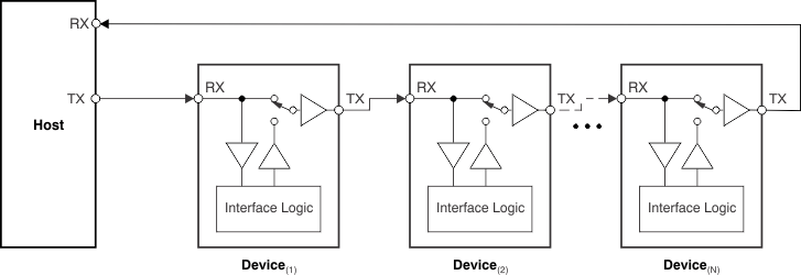
At device power-up, every TMP104 in the daisy-chain is connected in transparent mode, as shown in Figure 9. The host must send the initialization command (P7-P0 = 10001100) in order for the bus to program its internal address depending on the number of devices on the bus.
 Figure 9. TMP104 Daisy-Chain: Bus Status at Start of Global Initialization
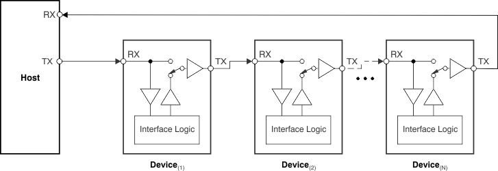
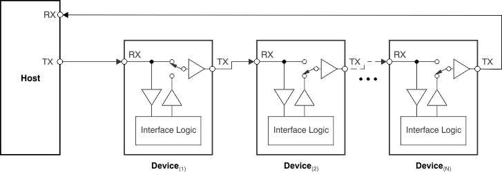
 Each TMP104 in the chain interprets the initialization command byte and disconnects the chain, as shown in Figure 10. The host must then send the address assignment command, consisting of P7-P4 = 1001 and P3-P0 = 0000, where P3-P0 represents the address of the first device in the chain; this word is stored internally as its device ID. The first device increments the unit in the device address and then reconnects the bus, as shown in Figure 11. This address is then sent to the next device in the chain. Once all devices on the chain have received the respective addresses, the host receives the last programmed address on the chain + 1. The host can use this information to determine the total number of devices in the chain and the respective address of each device.
After the initialization sequence, every device can be addressed individually or through global commands. This global initialization sequence is a requirement and must be performed before any other communication.
 Figure 10. TMP104 Daisy-Chain: Bus Status at Start of Address Assignment
  Figure 11. TMP104 Daisy-Chain: Bus Status After First Device Address Assignment