ZHCU831 November 2021 AWR2944 , IWR2944
2.4.4 Chirp Timing
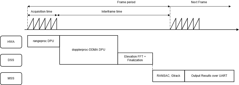
Figure 2-5 shows the timing of the chirps and subsequent processing in the system.

Figure 2-5 Chirp Timing Sequence
Chirp acquisition happens in the radar front end. The front end is configured via mmwavelink in accordance with the chirp configuration.
The core of the data path processing - from chirp acquisition to pointcloud output is divided into the following high-level blocks: rangeproc data processing unit (DPU), dopplerproc-DDMA DPU, elevation FFT, and finalization.
As the acquisition occurs, rangeproc DPU calculates the first dimensional FFT chirp-by-chirp in parallel to the acquisition, compresses the output, and stores it in memory as the compressed radarcube.
Next, the dopplerproc-DDMA DPU decompresses the radarcube one slice at a time and calculates for each slice both velocity and azimuth angle information by taking appropriate FFTs. The dopplerproc-DDMA DPU also performs DDMA demodulation to get the correct velocity out of six possible hypotheses as per the DDMA scheme. Finally, the dopplerproc-DDMA DPU also computes range CFAR and local maximum along range. The dopplerproc-DDMA DPU combines these to produce the object list. The dopplerproc-DDMA DPU utilizes both the hardware accelerator and DSP parallelly to achieve this.
After this step, the elevation FFT is performed on the DSP, followed by the finalization step that computes the Cartesian coordinates and velocity of the detected objects.
After this, RANSAC and GTrack algorithms run on the MSS to produce a target list for the scene. A brief overview of these algorithms is given in later sections. As Figure 2-5 shows, this part of the processing overruns into the next frame. This overrun is by design as it enables the parallel utilization of MSS for GTrack, RANSAC, and data transmission over UART while the rest of the processing happens on HWA+DSP for the next frame.
For more details on the application flow and processing, see the mmWave software development kit (SDK).