ZHCU831 November   2021 AWR2944


  1.   说明
  2.   资源
  3.   特性
  4.   应用
  5.   5
  6. 1System Description
    1. 1.1 Why use Radar?
    2. 1.2 TI Corner Radar Design
    3. 1.3 Key System Specification
  7. 2System Overview
    1. 2.1 Block Diagram
    2. 2.2 Design Considerations
    3. 2.3 Highlighted Products
      1. 2.3.1 AWR2944 Single-Chip Radar Solution
      2. 2.3.2 AWR2944 Evaluation Module
    4. 2.4 System Design Theory
      1. 2.4.1  Antenna Configuration
      2. 2.4.2  Chirp Configuration and System Performance
      3. 2.4.3  Data Path
      4. 2.4.4  Chirp Timing
      5. 2.4.5  eDMA Configuration
      6. 2.4.6  Memory Allocation
      7. 2.4.7  DDMA
      8. 2.4.8  Empty Subband Based DDMA
      9. 2.4.9  RANSAC
      10. 2.4.10 Group Tracker
  8. 3Hardware, Software, Testing Requirements, and Test Results
    1. 3.1 Required Hardware and Software
      1. 3.1.1 Hardware
      2. 3.1.2 Software and GUI
    2. 3.2 Test Setup
    3. 3.3 Test Results
  9. 4Design and Documentation Support
    1. 4.1 Design Files
      1. 4.1.1 Schematics
      2. 4.1.2 BOM
    2. 4.2 Tools and Software
    3. 4.3 Documentation Support
    4. 4.4 支持资源
    5. 4.5 Trademarks
  10. 5About the Author

Empty Subband Based DDMA

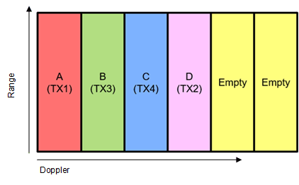
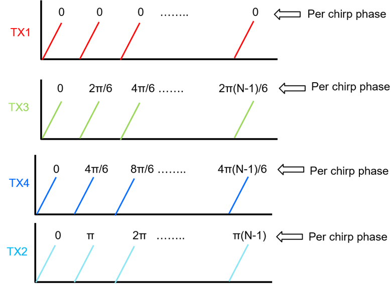
TX channels can be coded to introduce empty-bands in the Doppler spectrum. This allows more robust velocity disambiguation and Doppler-bin to TX-channel mapping in DDMA. To introduce two empty Doppler subbands, the phase added to each TX channel is modified as ω k = 2 π ( k - 1 ) N t + 2 . Figure 2-8 and Figure 2-9 show the range-Doppler plane with N t = 4 and two empty-bands. The locations of these empty Doppler subbands are used to find the hypothesis that will determine the correct TX channel mapping and allow velocity disambiguation as shown in Figure 2-10.

GUID-20211110-SS0I-2G6M-5SQ3-NJLWHCF5QMFJ-low.png

Figure 2-8 DDMA Modulation
GUID-20211111-SS0I-TTKP-6RXR-KJDLQ9GWFW8D-low.gifFigure 2-9 Doppler Spectrum in DDMA With 4 Transmitters and 2 Empty Subbands

GUID-20211111-SS0I-W7FJ-7PPM-QX7W3TL960FX-low.gif

Figure 2-10 Different Hypothesis Corresponding to Different Empty Band Locations