TIDUEX1A December   2020  – March 2021


  1.   Description
  2.   Resources
  3.   Features
  4.   Applications
  5.   5
  6. 1System Description
    1. 1.1 Key System Specifications
  7. 2System Overview
    1. 2.1 Block Diagram
    2. 2.2 Design Considerations
    3. 2.3 Highlighted Products
      1. 2.3.1 TMP117 – High-accuracy, low-power, digital temperature sensor
      2. 2.3.2 System Design Theory
        1. 2.3.2.1 System Accuracy
  8. 3Hardware, Software, Testing Requirements, and Test Results
    1. 3.1 Hardware
    2. 3.2 Software
      1. 3.2.1 SysConfig
      2. 3.2.2 Graphical User Interface (GUI)
        1. 3.2.2.1 Launching and Running the Software
        2. 3.2.2.2 Using the GUI
          1. 3.2.2.2.1 Home Tab
          2. 3.2.2.2.2 Data Capture Tab
          3. 3.2.2.2.3 EVM Setup Tab
          4. 3.2.2.2.4 Configuration Tab
          5. 3.2.2.2.5 Register Tab
          6. 3.2.2.2.6 Collateral Tab
    3. 3.3 Testing and Results
      1. 3.3.1 Test Setup
        1. 3.3.1.1 System Accuracy
      2. 3.3.2 Test Results
  9. 4Design and Documentation Support
    1. 4.1 Design Files
      1. 4.1.1 Schematics
      2. 4.1.2 BOM
    2. 4.2 Tools and Software
      1. 4.2.1 PCB Layout Recommendations
      2. 4.2.2 Software Files
    3. 4.3 Documentation Support
    4. 4.4 Support Resources
    5. 4.5 Trademarks
  10. 5Revision History
EVM Setup Tab

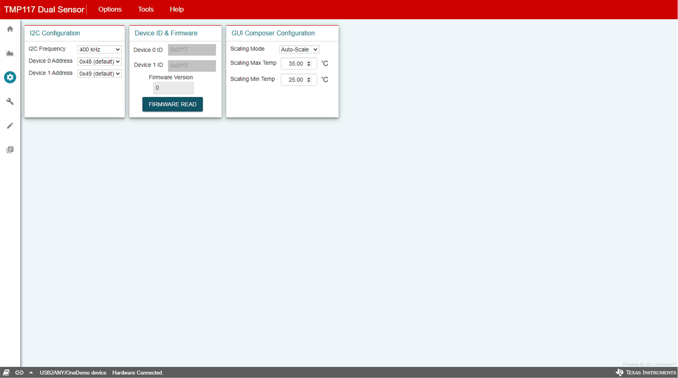
The EVM Setup tab shown in Figure 3-11 is where the I2C settings are set and firmware version and Device ID can be read. It is necessary to configure the TMP117 slave address as 0x48 and 0x49 for communication with the reference design.

  • Alert High and Low Limit Register can be set by entering the value in °C or °F based on °C/°F control on the Data Capture tab that stores the high and low limits for comparison with the temperature result.
  • Offset Temperature programs the offset temperature to compensate and improve the system error. This register will be cleared when powered down unless the LOCK is set.
  • Firmware Read checks the firmware revision on the MSP430F5528 microcontroller.

    I2C Configuration changes the bus frequency and slave address.

  • Device ID automatically read device identification.
  • Software Reset performs a software reset on the TMP117 devices by issuing a general call. After, the software reset, the values displayed in the EVM software may be out of sync with the device register contents. To sync register contents after TMP117 reset, click "Read All" in the Registers tab page.
GUID-20200811-CA0I-FGBJ-JWK0-PSMKSF9D0K27-low.gifFigure 3-11 EVM Setup Page