TIDUEX1A December   2020  – March 2021


  1.   Description
  2.   Resources
  3.   Features
  4.   Applications
  5.   5
  6. 1System Description
    1. 1.1 Key System Specifications
  7. 2System Overview
    1. 2.1 Block Diagram
    2. 2.2 Design Considerations
    3. 2.3 Highlighted Products
      1. 2.3.1 TMP117 – High-accuracy, low-power, digital temperature sensor
      2. 2.3.2 System Design Theory
        1. 2.3.2.1 System Accuracy
  8. 3Hardware, Software, Testing Requirements, and Test Results
    1. 3.1 Hardware
    2. 3.2 Software
      1. 3.2.1 SysConfig
      2. 3.2.2 Graphical User Interface (GUI)
        1. 3.2.2.1 Launching and Running the Software
        2. 3.2.2.2 Using the GUI
          1. 3.2.2.2.1 Home Tab
          2. 3.2.2.2.2 Data Capture Tab
          3. 3.2.2.2.3 EVM Setup Tab
          4. 3.2.2.2.4 Configuration Tab
          5. 3.2.2.2.5 Register Tab
          6. 3.2.2.2.6 Collateral Tab
    3. 3.3 Testing and Results
      1. 3.3.1 Test Setup
        1. 3.3.1.1 System Accuracy
      2. 3.3.2 Test Results
  9. 4Design and Documentation Support
    1. 4.1 Design Files
      1. 4.1.1 Schematics
      2. 4.1.2 BOM
    2. 4.2 Tools and Software
      1. 4.2.1 PCB Layout Recommendations
      2. 4.2.2 Software Files
    3. 4.3 Documentation Support
    4. 4.4 Support Resources
    5. 4.5 Trademarks
  10. 5Revision History

System Design Theory

This design features headers to connect an MCU for communication to the TMP117 devices and inputs to a speaker as shown in Figure 2-4. There are also integrated speaker soldering pads towards the end to solder on a small speaker as shown in Figure 2-5. The two TMP117 are used to collect temperature data determine body temperature of the user.

GUID-A4EDAF07-9CB0-4AAE-A31C-17C35F6E9AC1-low.gif Figure 2-4 MCU and Speaker Input Headers
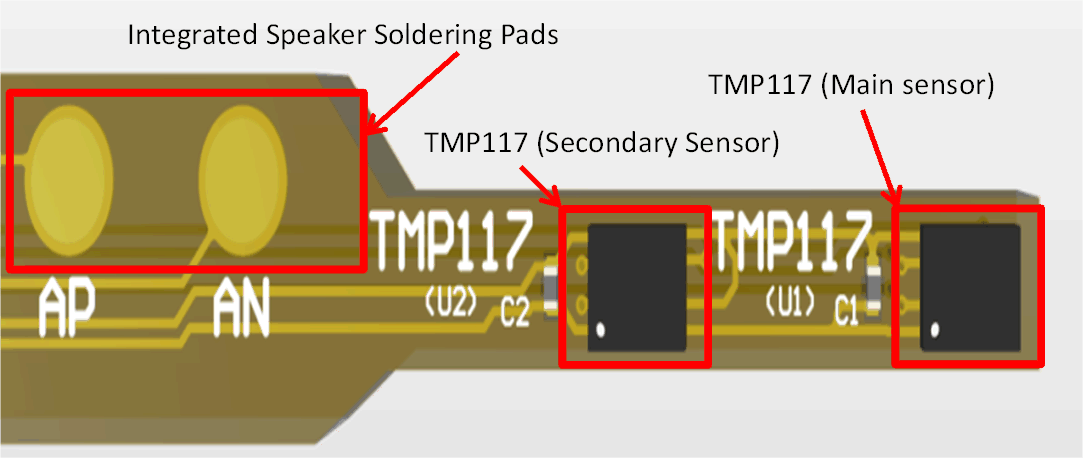
GUID-20200810-CA0I-WH64-S4CN-SLZK4K1SLS6P-low.gif Figure 2-5 Integrated Speaker Soldering pads and TMP117 devices