TIDUEX1A December   2020  – March 2021


  1.   Description
  2.   Resources
  3.   Features
  4.   Applications
  5.   5
  6. 1System Description
    1. 1.1 Key System Specifications
  7. 2System Overview
    1. 2.1 Block Diagram
    2. 2.2 Design Considerations
    3. 2.3 Highlighted Products
      1. 2.3.1 TMP117 – High-accuracy, low-power, digital temperature sensor
      2. 2.3.2 System Design Theory
        1. 2.3.2.1 System Accuracy
  8. 3Hardware, Software, Testing Requirements, and Test Results
    1. 3.1 Hardware
    2. 3.2 Software
      1. 3.2.1 SysConfig
      2. 3.2.2 Graphical User Interface (GUI)
        1. 3.2.2.1 Launching and Running the Software
        2. 3.2.2.2 Using the GUI
          1. 3.2.2.2.1 Home Tab
          2. 3.2.2.2.2 Data Capture Tab
          3. 3.2.2.2.3 EVM Setup Tab
          4. 3.2.2.2.4 Configuration Tab
          5. 3.2.2.2.5 Register Tab
          6. 3.2.2.2.6 Collateral Tab
    3. 3.3 Testing and Results
      1. 3.3.1 Test Setup
        1. 3.3.1.1 System Accuracy
      2. 3.3.2 Test Results
  9. 4Design and Documentation Support
    1. 4.1 Design Files
      1. 4.1.1 Schematics
      2. 4.1.2 BOM
    2. 4.2 Tools and Software
      1. 4.2.1 PCB Layout Recommendations
      2. 4.2.2 Software Files
    3. 4.3 Documentation Support
    4. 4.4 Support Resources
    5. 4.5 Trademarks
  10. 5Revision History

Hardware

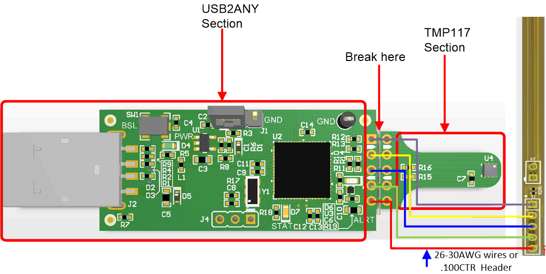
The hearable flex board and a separate MCU are needed to test the design. The headers for the MCU were made to align with the headers on the TMP117EVM. The TMP117EVM can be broken into two sections: one with the TMP117 and the other with the USB2ANY as shown in Figure 3-1.

The USB2ANY portion can be used to communicate to both TMP117 devices using the TMP117DualSensor_GUI which can be found at the Texas Instruments Gallery. The main sensor's 7-bit I2C address is 0x49 and the secondary sensor's 7-bit I2C address is 0x48.
GUID-20200814-CA0I-QTT6-7H5X-CGSV9FVJ509H-low.gif Figure 3-1 Connecting to TMP117EVM