TIDT260 March 2022
2.5 Bode Plots
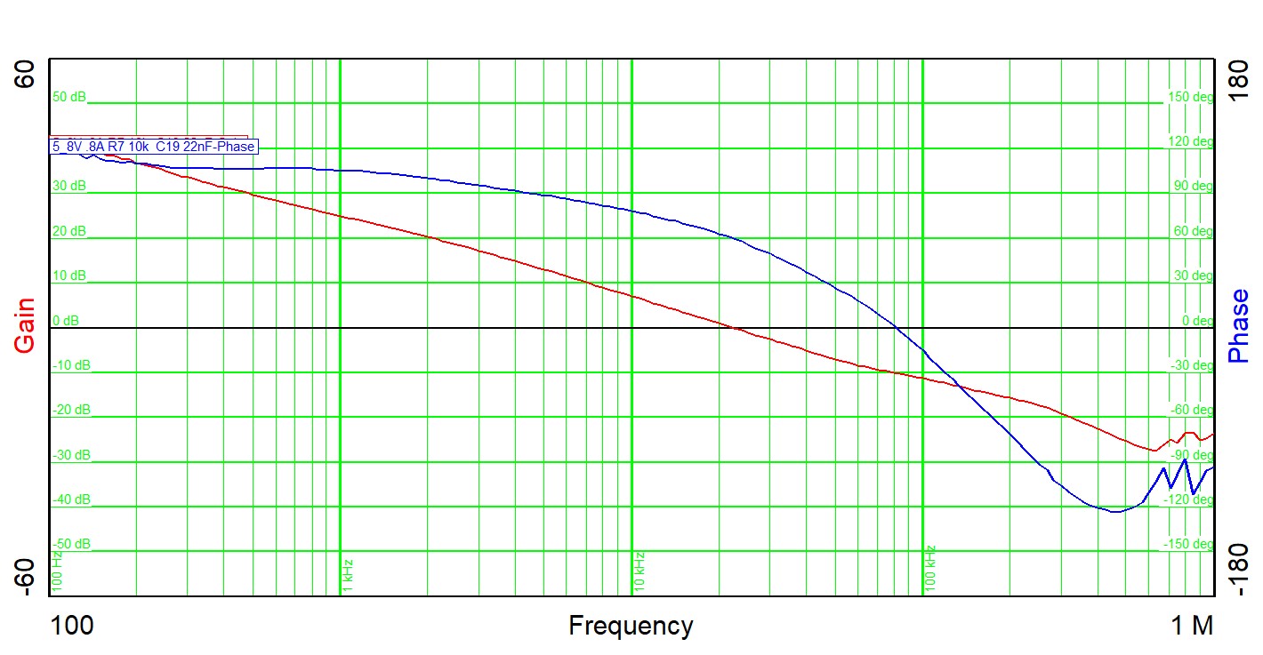
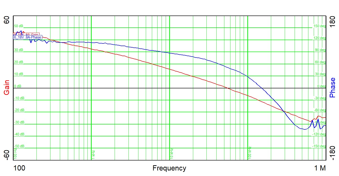
Figure 2-10 and Figure 2-11 show the PMP31139 bode plots. R7 is reduced to 10 kΩ, C19 is increased to 22 nF – maximum loop bandwidth.
 Figure 2-10 Bode Plot at 8-VIN
0.8-AOUT
 Figure 2-11 Bode Plot at 18 VIN, 0.8
AOUT
Figure 2-11 Bode Plot at 18 VIN, 0.8
AOUT| VIN | 8 V | 18 V |
|---|---|---|
| Bandwidth (kHz) | 22 | 55 |
| Phase Margin | 59.8° | 51.5° |
| Slope (20 dB/decade) | –1 | –1.5 |
| Gain Margin (dB) | –10 | –11 |
| Slope (20 dB/decade) | –0.63 | –1.5 |
| Freq (kHz) | 81 | 150 |
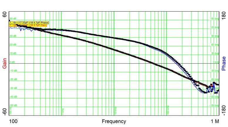
A loop modification is made, tuning the poles.
The gain of LM5158 increases at bigger input voltage, crossover frequency Fco = 55 kHz at 18-V input. To keep the loop bandwidth around 20 kHz at 8-V input voltage the two poles have been adjusted, RC corner frequency is set around 500 kHz, C17 = 33 pF and C18 = 4.7 pF.
The roll off of the phase has been stretched, achieving a better phase margin of 55 degrees,
 Figure 2-12 Bode Plot
| 18 VIN | 18 VIN New | |
|---|---|---|
| Bandwidth (kHz) | 55.0 | 55.9 |
| Phase Margin | 51.5° | 55.4° |
| Slope (20 dB/decade) | –1.5 | –1.2 |
| Gain Margin (dB) | –11.0 | –11.9 |
| Slope (20 dB/decade) | –1.50 | –1.44 |
| Freq (kHz) | 150 | 167 |