SWRU596 December 2022
- 1Abstract
- 2Getting Started
- 3Hardware
- 4EVM Mux Block Diagram
- 5PCB Storage and Handling Recommendations:
- 6XWRL6432BOOST Antenna
- 7Software, Development Tools, and Example Code
- 8TI E2E Community
- 9References
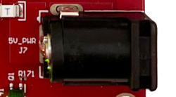
6.4 Connectors
Higher current support: When using the EVM with the external power adaptor, the 5-V supply is provided by the external power adaptor. For most of the use-cases this external power supply option is not used, power is derived from the USB interface.
Note: After the 5-V power supply is provided to the EVM, TI
recommends pressing the NRST switch one time to ensure a reliable boot-up
state.
Note: All digital IO pins of the device (except NRESET) are
non-failsafe; hence, care needs to be taken that they are not driven externally
without the VIO supply being present to the device.