SWRU596 December 2022
- 1Abstract
- 2Getting Started
- 3Hardware
- 4EVM Mux Block Diagram
- 5PCB Storage and Handling Recommendations:
- 6XWRL6432BOOST Antenna
- 7Software, Development Tools, and Example Code
- 8TI E2E Community
- 9References
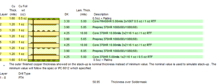
6.1 PCB material
Material used for this PCB is FR408HR ½ oz dual ply 2x1067 spread glass construction for the Antenna and transmission lines and 370HR is used for the rest of the layers.