SWRU359F September   2015  – December 2021 WL1801MOD , WL1805MOD , WL1831MOD , WL1835MOD


  1.   Trademarks
  2.   Warning
  3. 1Introduction
    1. 1.1 Features
    2. 1.2 Applications
    3. 1.3 TI Module Key Benefits
  4. 2Board Pin Assignment
    1. 2.1 Pin Descriptions
  5. 3Electrical Characteristics
  6. 4Approved Antenna Types and Maximum Gain Values
  7. 5On-Board Antenna Configuration
    1. 5.1 VSWR
    2. 5.2 Efficiency
    3. 5.3 Radio Pattern
    4. 5.4 ANT1
    5. 5.5 ANT2
  8. 6Circuit Design
    1. 6.1 Schematic
    2. 6.2 Bill of Materials (BOM)
  9. 7Layout Guidelines
    1. 7.1 Board Layout
  10. 8Revision History

ANT1

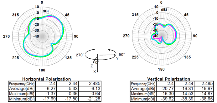
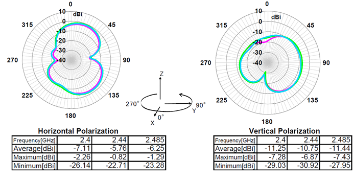
Figure 5-4 shows the ANT1 polarization of the WL1835MODCOM8B device.
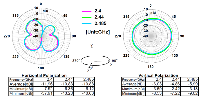
GUID-1EC5CDED-2675-41D8-8D20-692DEC002042-low.pngFigure 5-4 ANT1 Polarization
GUID-D3BDC6A4-7490-487E-8A8D-C9F7B511F71D-low.pngFigure 5-5 ANT1 Polarization
GUID-E249E69D-40D4-4DBF-85E2-846C672B2519-low.pngFigure 5-6 ANT1 Polarization