SWRA534A January 2017 – June 2017 CC2650MODA
2.2 Hardware Setup
Use the following instructions to set up the hardware.
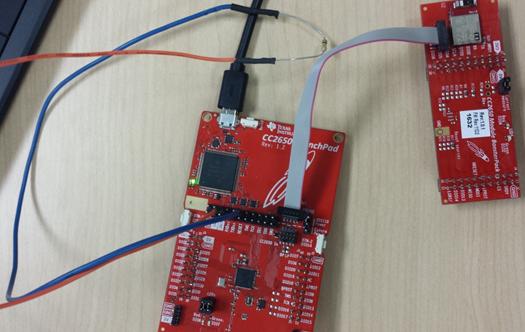
- Connect the 10-pin JTAG cable to the JTAG pins on the CC2650 module, then connect the other end of the cable to the XDS110 Out pins on the CC2650 LaunchPad (see Figure 1).
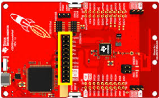
- Ensure that the necessary jumpers are removed to isolate the XDS110 from the onboard CC2650 of the LaunchPad (see the yellow box in Figure 2). Also, verify that the XDS110 power jumper is selected to supply power to the CC2650 module.
- Insert a 100-k resistor between the 3V3 and reset pins on the XDS side of the JTAG-CC2650 jumper header on the launchpad (see the orange and blue headers in Figure 1).
 Figure 1. CC2650 Module to CC2650 LaunchPad Connection
 Complete step 3 only if using revision 1.2 or later of the CC2650 LaunchPad.
Step 3 is required with revision 1.2 or later because the CC2650 Module BoosterPack was designed as a BoosterPack to work with a LaunchPad.
 Figure 2. Jumpers to Remove on CC2650 LaunchPad
 After completing the previous steps, the provided micro-USB cable can be used to power and program the CC2650 module as detailed in the software developer's guide.