SPRZ272N September 2007 – April 2022 SM320F28335-EP , SM320F28335-HT , TMS320F28232 , TMS320F28232-Q1 , TMS320F28234 , TMS320F28234-Q1 , TMS320F28235 , TMS320F28235-Q1 , TMS320F28332 , TMS320F28333 , TMS320F28334 , TMS320F28335 , TMS320F28335-Q1
- 1Usage Notes and Advisories Matrices
- 2Nomenclature, Package Symbolization, and Revision Identification
-
3Silicon Revision A Usage Notes and
Advisories
- 3.1
Silicon Revision A Usage Notes
- 3.1.1 PIE: Spurious Nested Interrupt After Back-to-Back PIEACK Write and Manual CPU Interrupt Mask Clear Usage Note
- 3.1.2 Caution While Using Nested Interrupts
- 3.1.3 Watchdog: Watchdog Issues Reset After Bad Key is Written
- 3.1.4 McBSP: XRDY Bit can Hold the Not-Ready Status (0) if New Data is Written to the DX1 Register Without First Verifying if the XRDY Bit is in its Ready State (1)
- 3.1.5 Maximum Flash Program Time and Erase Time in Revision O of the TMS320F2833x, TMS320F2823x Real-Time Microcontrollers Data Sheet
- 3.2 Silicon Revision A Advisories
- 3.1
Silicon Revision A Usage Notes
- 4Silicon Revision 0 Usage Notes and Advisories
- 5Documentation Support
- 6Trademarks
- 7Revision History
Advisory
SCI: Incorrect Operation of SCI in Address Bit Mode
Revision(s) Affected
0, A
Details
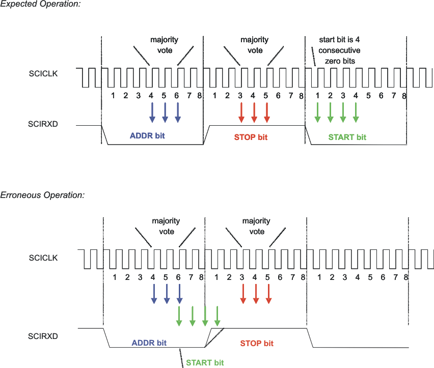
SCI does not look for STOP bit after the ADDR bit. Instead, SCI starts looking for the start bit beginning on sub-sample 6 of the ADDR bit. Slow rise-time from ADDR to STOP bit can cause the false START bit to occur since the 4th sub-sample for the start bit may be sensed low.
 Figure 3-1 Difference Between Expected and Erroneous Operation of START Bit
Workaround(s)
Program the baud rate of the SCI to be slightly slower than the actual. This will cause the 4th sub-sample of the false START bit to be delayed in time, and therefore occur more towards the middle of the STOP bit (away from the signal transition region). The amount of baud slowing needed depends on the rise-time of the signal in the system. Alternatively, IDLE mode of the SCI module may be used, if applicable.