SNVU731 November 2020 LP8864-Q1
2.6.2 Diagnostics Page
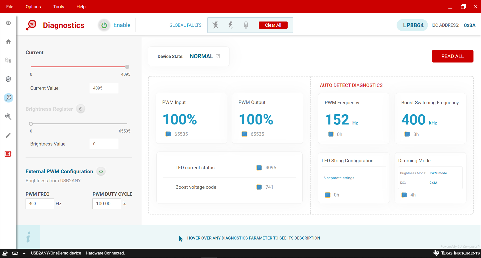
From the Diagnostics page (see Figure 2-7), the user can read back the following diagnostics register values and corresponding device status.
- FSM_LIVE_STATUS: current status of the functional state machine
- PWM_INPUT_STATUS: 16-bit value for detected duty cycle of PWM input signal
- PWM_OUTPUT_STATUS: 16-bit value for configured duty cycle of PWM output signal
- LED_CURRENT_STATUS: 12-bit current DAC code that brightness path is driving to OUT1-4 output
- VBOOST_STATUS: 11-bit boost voltage code that adaptive voltage control loop sending to analog boost block
- AUTO_PWM_FREQ_SEL: LED PWM frequency value from PWM_SEL resistor detection
- AUTO_LED_STRING_CFG: LED string configuration from LED_SET resistor detection
- AUTO_BOOST_FREQ_SEL: boost switching frequency value from PWM_FSET resistor detection
- MODE_SEL: LED dimming mode value from MODE resistor detection
 Figure 2-7 LP8864VM Diagnostics
Page