SNLU313 August 2022 DP83TG720R-Q1 , DP83TG720S-Q1
2.1.1 Setup
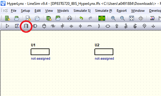
- Open HyperLynx and create a new SI or SI/PI schematic.
- Place two IC components from the toolbar.
- Double click each
component. Click "Library Path..." then "Add" to specify the location of the
dp83tg720r.ibs file. Click "OK".
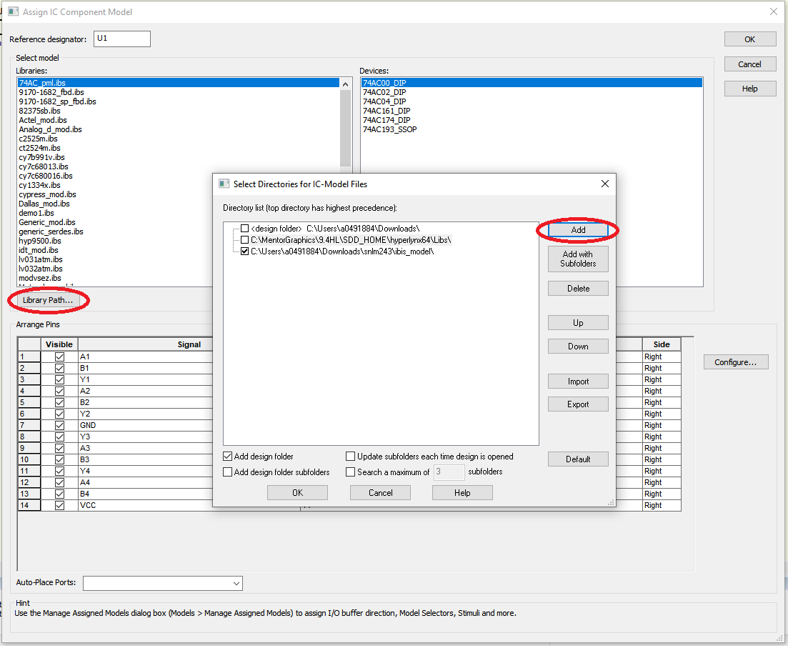
- Select the
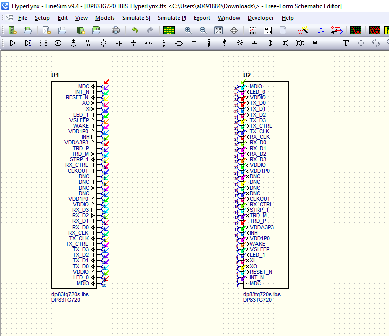
dp83tg720r.ibs file and click Ok. Do the same for the other IC component. Right
click on U2 and rotate twice.
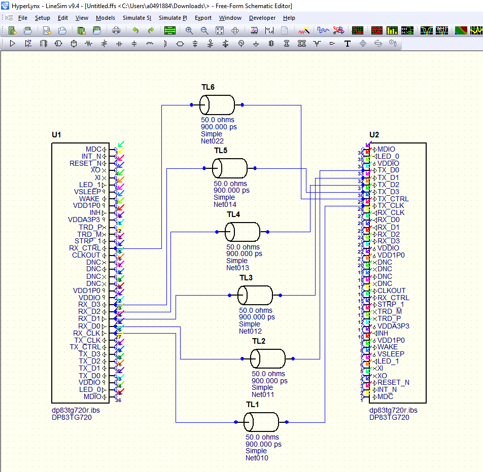
- In this example, the
RGMII connections will be made using an ideal transmission line as the channel.
A following section will show how to upload custom S parameter files to
simulation actual PCB designs. For now, place a transmission line component from
the toolbar and use it to connect RX_CLK and TX_CLK as shown below.
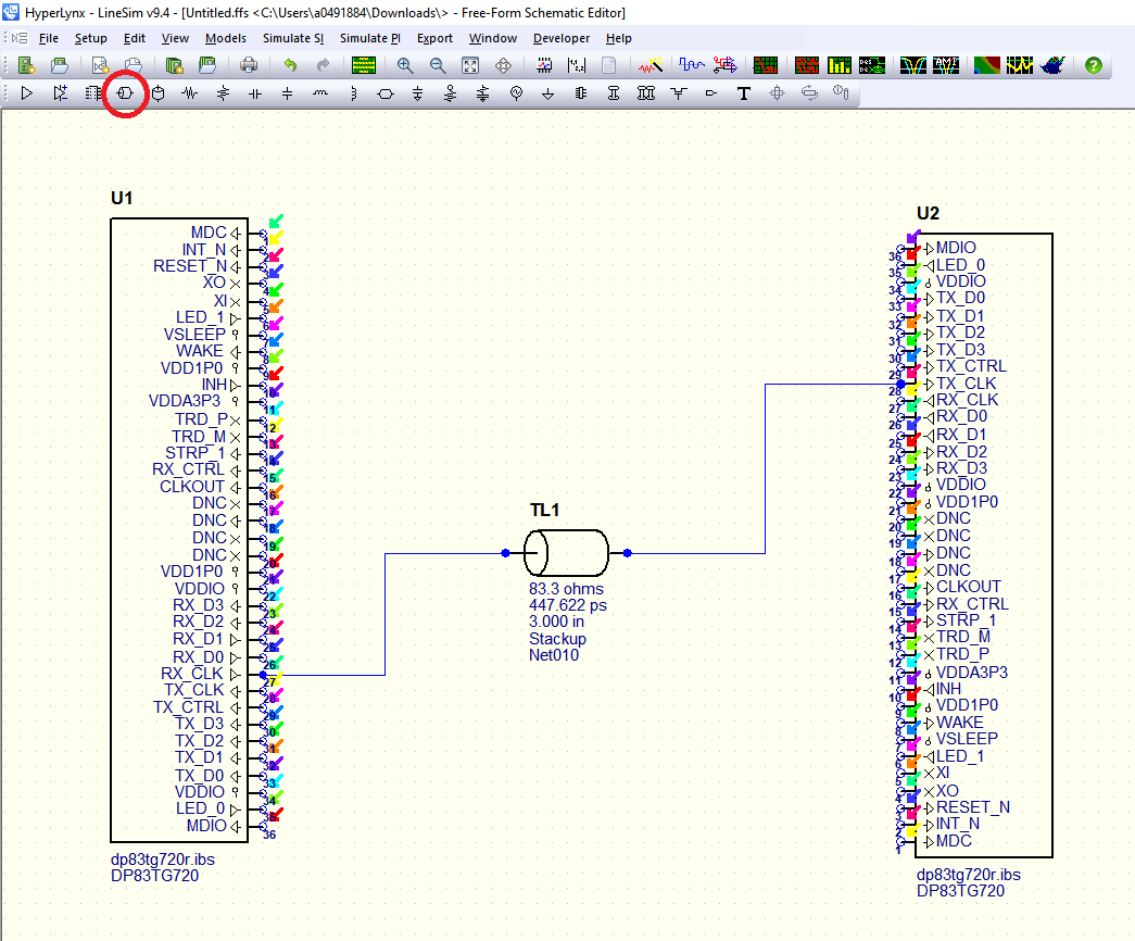
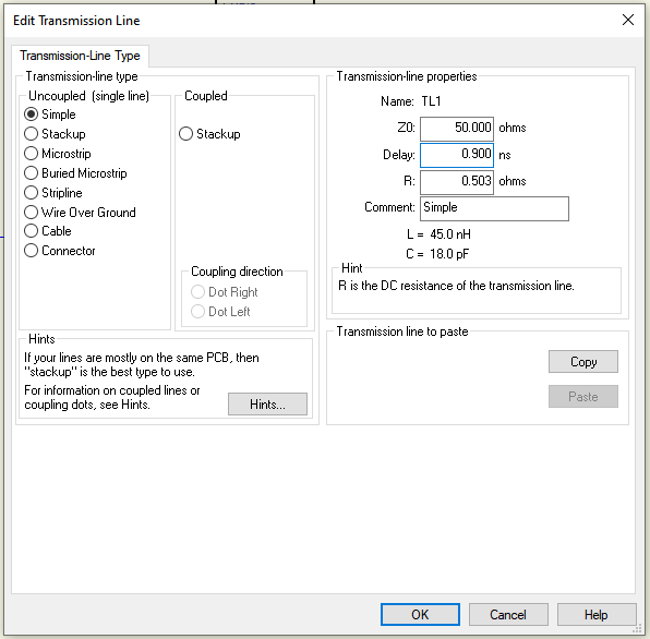
- Double click TL1 and
change the type to Simple. Set the transmission line parameters as desired.
Click "OK."
- Copy and Paste TL1 five
more times and make the following connections.
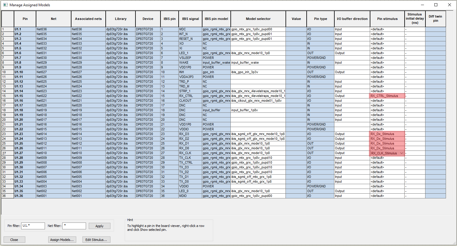
- Right click U1 and
select "Manage Model selectors, Buffer directions and Stimuli..." Specify the
Model selector, I/O buffer direction, and Pin stimulus.
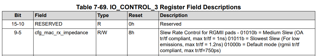
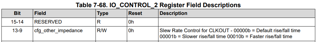
Each pin in the IBIS file has several different selectable models, based on the operating levels of the power supplies and adjustable termination values. The DP83TG720 has adjustable impedance control for RGMII signaling pads and CLKOUT pin, to allow for slew rate control. Reference the readme_ibis_dp83tg720r.xlsx file to select which one to use. Slow and slowest modes will decrease the rise and fall times of each signal. The different models correspond to the cfg_mac_rx_impedance bits in register 0x0456, and cfg_other_impedance bits in register 0x455 in the data sheet.
- This case will use a Vddio level of 1.8V and
default termination, so leave the default model selectors for each pin.
Under the I/O buffer drop-down, select Output for all six of the relevant pins.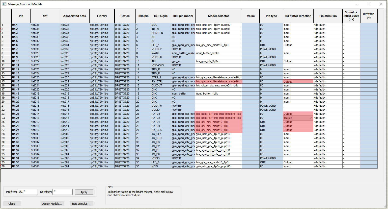
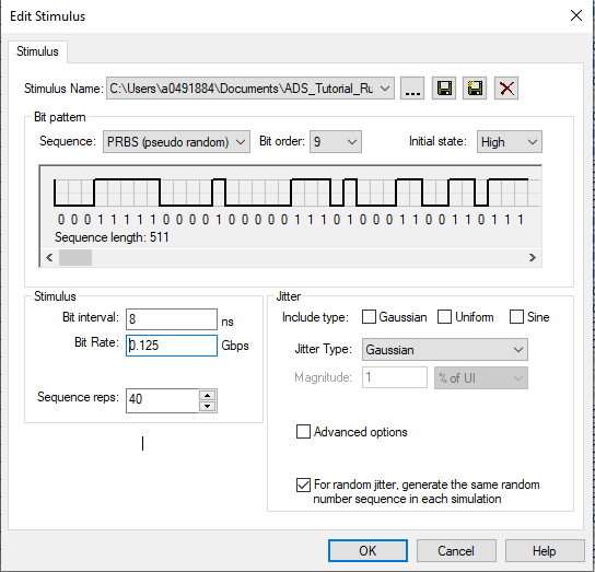
- Click the "Edit Stimulus..." button in the lower left corner. Create an oscillator stimulus for the RX_CLK output, and PRBS stimulus for the RX_Dx outputs to emulate actual RGMII data transmission.
- To emulate the RX_CLK signal, select “Oscillator”
from the drop down menu, and enter a frequency of 0.125GHz, and increase the
sequence reps to 4000. Click the Save button and save this as “RX_CLK
_Stimulus.eds”
Change the sequence dropdown to PRBS. Select bit order 9. Save this file as “RX_Dx_Stimulus.eds”
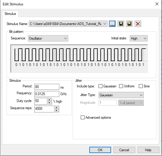
Finally, create a 12.5MHz oscillator for the RX_CTRL output and name it.
“RX_CTRL_Stimulus.eds”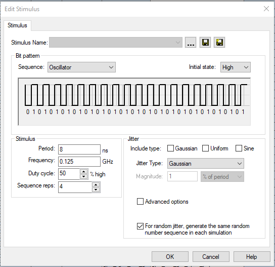
- Click "OK" to return to
the previous screen, and assign the new stimuli to their respective pins. Click
the close button.
- No additional configuration is required on U2, but confirm that the connected pins are selected as inputs. The model is now ready to simulate.