SNLU313 August 2022 DP83TG720R-Q1 , DP83TG720S-Q1
2.1.2 Measurements
- Click the button in the toolbar to open the
waveform window.
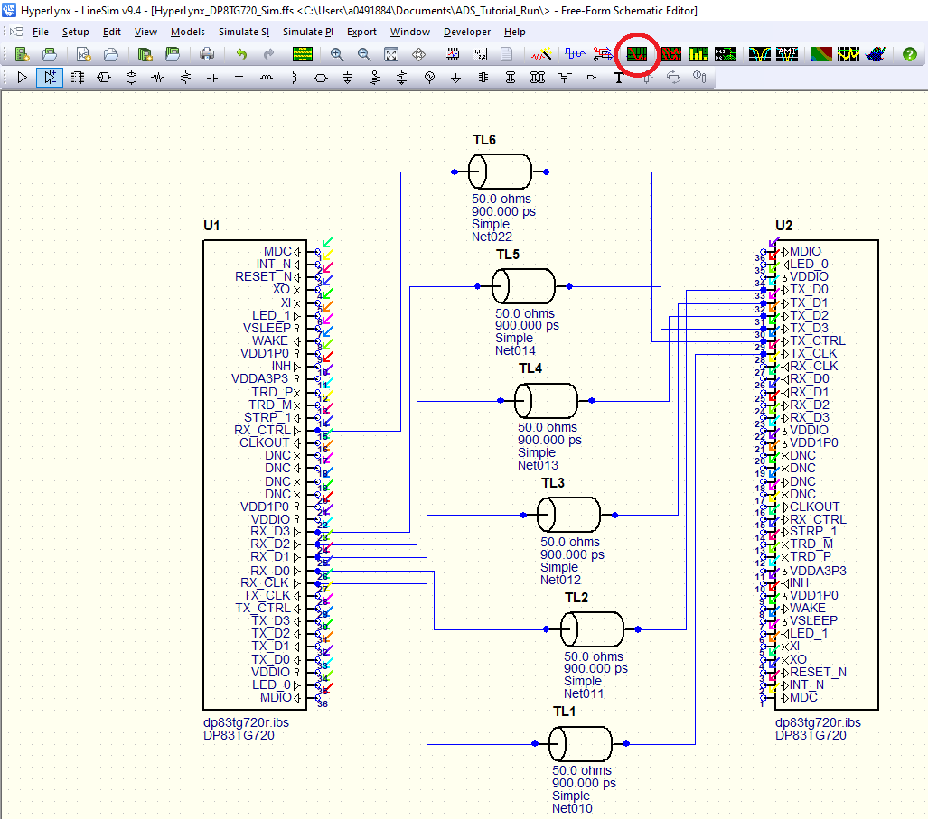
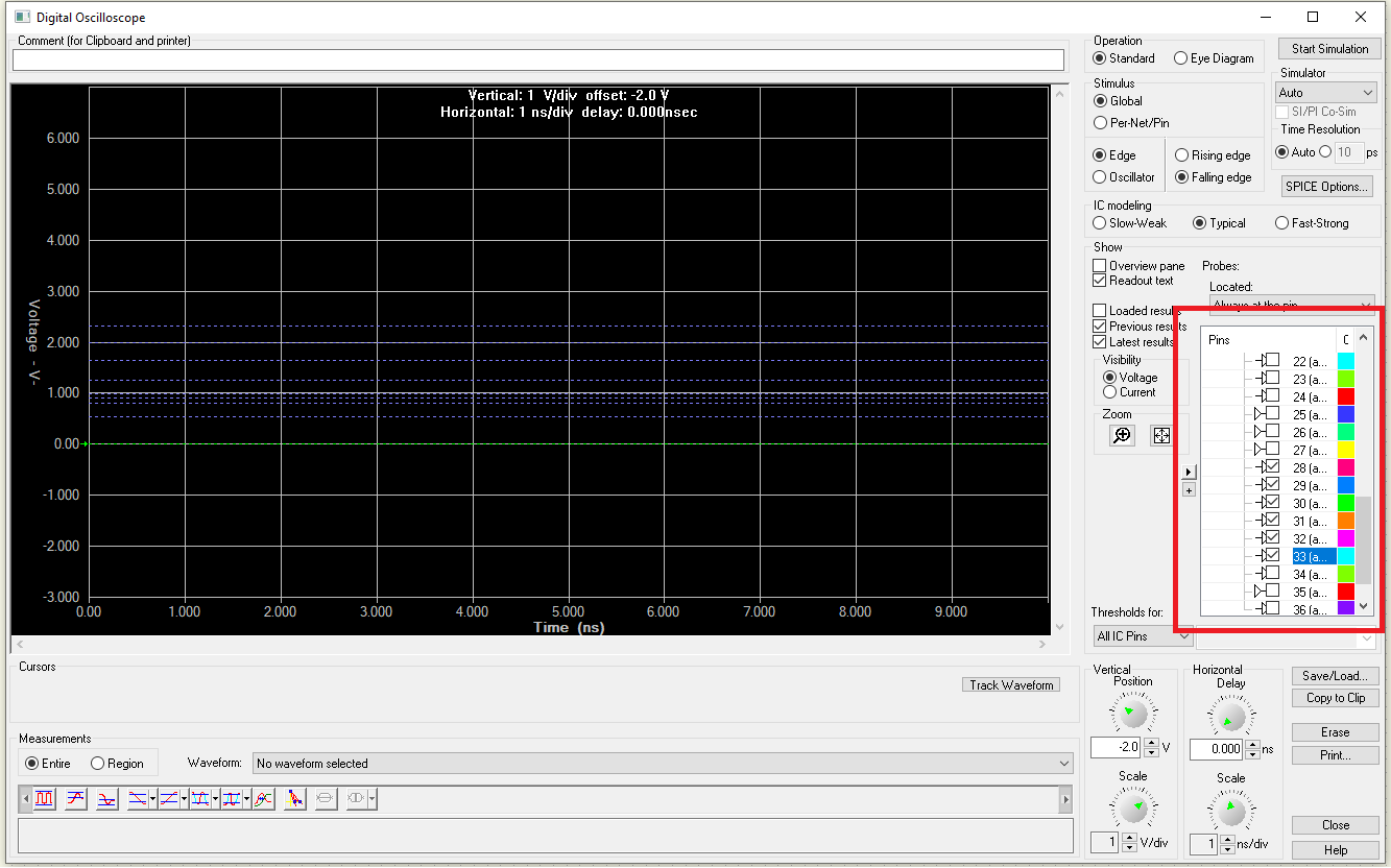
- Select which pins to view waveforms of. Click the
triangle to the left of the pins box and click "Disable all probes." Select pins
28-33 on U2.
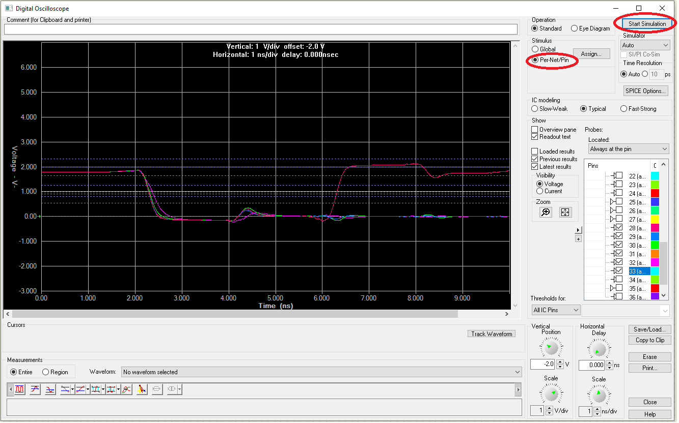
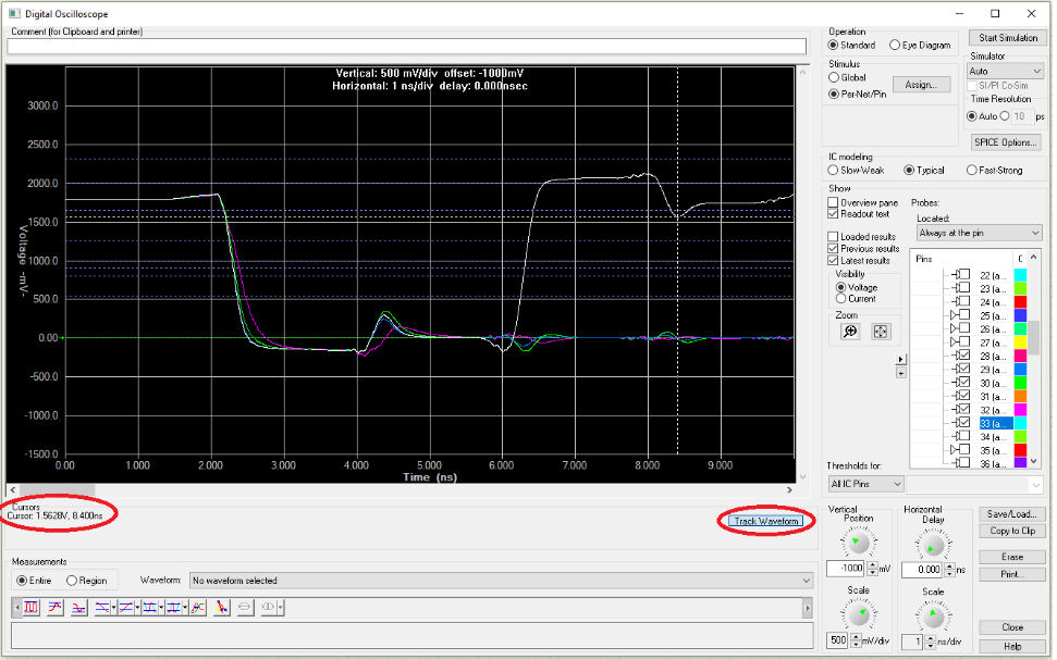
- Under the stimulus selector, choose "Per-Net/Pin"
to allow the individual stimuli selected earlier. Click the Start Simulation
button. The following waveforms will appear.
- Use the up and down arrows under the dials to
adjust the view of the waveform.
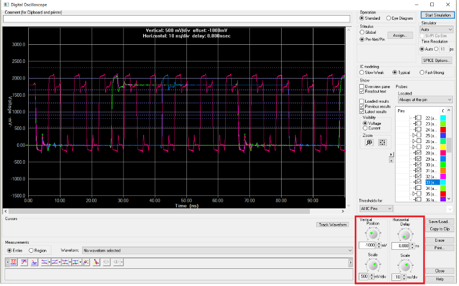
- Any time or voltage value can be gathered from
this plot manually. Click the Track Waveform button and click on a waveform. The cursor
information will be shown here.
- To acquire automatic measurements, select a waveform and measurement option in the bottom left. Options include peak-to-peak voltage, rise/fall times, positive/negative overshoot, etc.