SNLU313 August 2022 DP83TG720R-Q1 , DP83TG720S-Q1
2.1.3 Further Configuration
The previous sections cover the basics of HyperLynx simulations. Additional configuration options follow. By default, the previous waveforms are shown to allow an easy comparison of any changes made.
- Change the IC modeling option to Slow-Weak or Fast-Strong. Notice the rise/fall times increase and decrease respectively, and there is less and more overshoot respectively. This setting is used to simulate all process corners of silicon manufacturing.
- Set the location at the pin or at the die. This will choose whether to include the package characteristics or not.
- Go back to the main window and change the model selector or stimuli for the desired pins.
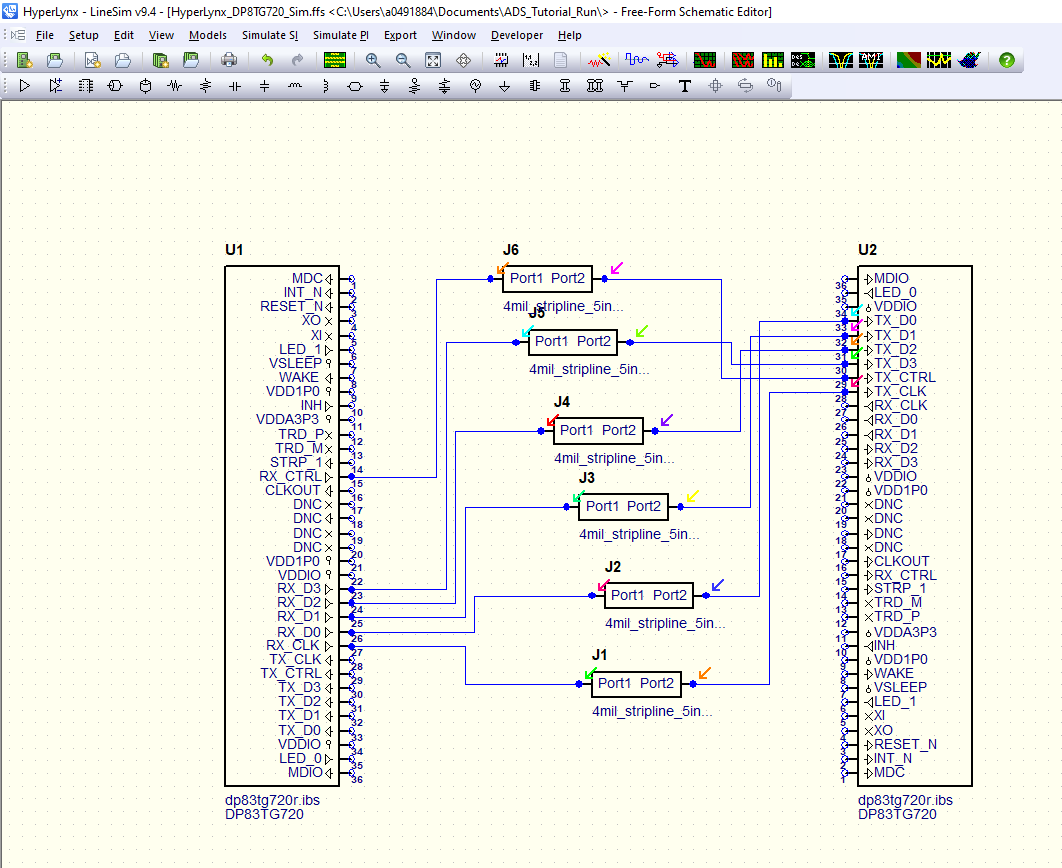
- Change the transmission line characteristics
In most cases, it will be beneficial to use actual S-Parameters of PCB traces instead of ideal transmission lines. Select the S-Parameter option from the toolbar and replace each transmission line with this. Double click the J1 item and select your desired S-Parameter file. This example is using a 5 inch, 4 mil FR4 trace file. Return to the simulation window and re-simulate.