SNAA266A April 2015 – November 2015 TDC1000 , TDC1000-Q1 , TDC1011 , TDC1011-Q1
4 Tank design modifications to accommodate transducer
The previous section discussed the process of mounting a transducer externally to a tank for prototyping purposes. This section discusses some considerations to take into account when modifying a tank to accommodate an unsealed transducer. The tank design modification consists of creating a receptacle or mounting "well" where the transducer can be protected from external damage and allow for acoustic dampening material to increase short range performance. Below are some mechanical drawings to consider when modifying a tank design. For the following discussion I'll be utilizing a 2.1mm thick transducer. The adhesive considerations are the same as discussed in the above sections.
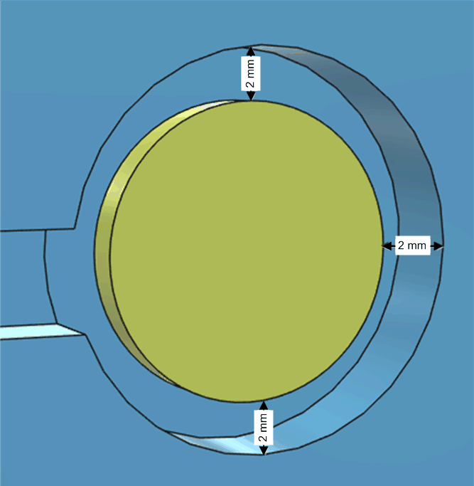
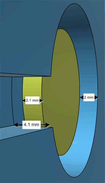
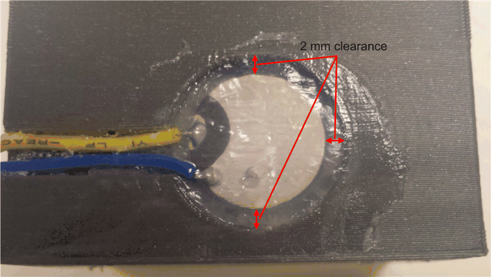
The first consideration is to leave enough space radially around the transducer to prevent radial vibrations from propagating into the tank wall in the direction opposite from what's required for a level measurement. As is shown below a 2mm clearance should easily achieve this and allow an acoustic dampening material (in this case RTV silicone) to enter the gap and help dissipate radial vibrations. The next consideration is to recess the transducer into the tank wall deeply enough to allow for a minimum of 1x the transducer thickness of acoustic dampening material (RTV etc.). For the example below the transducer receptacle is depressed approximately 4.1mm in from the tank's outer wall. Deeper recession may help reduce the transducer ring-down depending on the dampening material and tank construction.
 Figure 6. Transducer Receptacle Clearance (Front View)
  Figure 7. Transducer Receptacle Clearance (Side View)
  Figure 8. Transducer Receptacle (Top View)
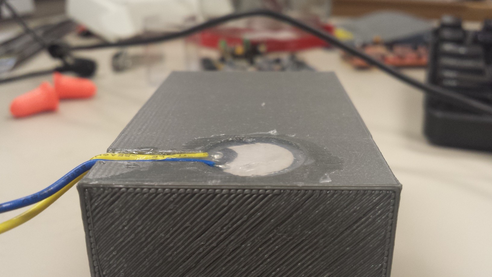
  Figure 9. Transducer Receptacle (Side View)