SLVUBZ2A September 2020 – December 2020 LM5127-Q1
1 Introduction
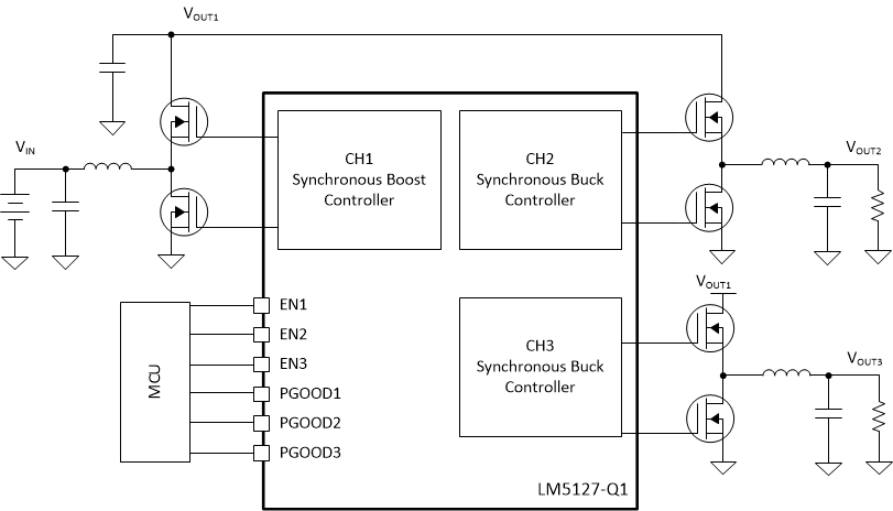
The LM5127EVM-FLEX is designed for use with a wide input voltage range of 3 V to 42 V to produce two tightly regulated output voltages of 5 V at 5 A and 3.3 V at 7 A. Figure 1-1 shows the standard configuration of the LM5127EVM-FLEX. It is configured as a typical front end power supply in 12 V automotive applications. Channel 1 implements a synchronous pre-boost, supplying adequate voltage for the two synchronous buck controllers (channel 2 / channel 3) to maintain output regulation for input voltage transients as low as 3 V. The free-running switching frequency is 440 kHz and synchronization to an external clock signal is possible at higher or lower frequency. The main discrete power-train components (inductors and MOSFETs) are automotive AEC-Q200 rated.
 Figure 1-1 Typical Application
Circuit