SLVUBZ2A September 2020 – December 2020
4 Testing Procedures
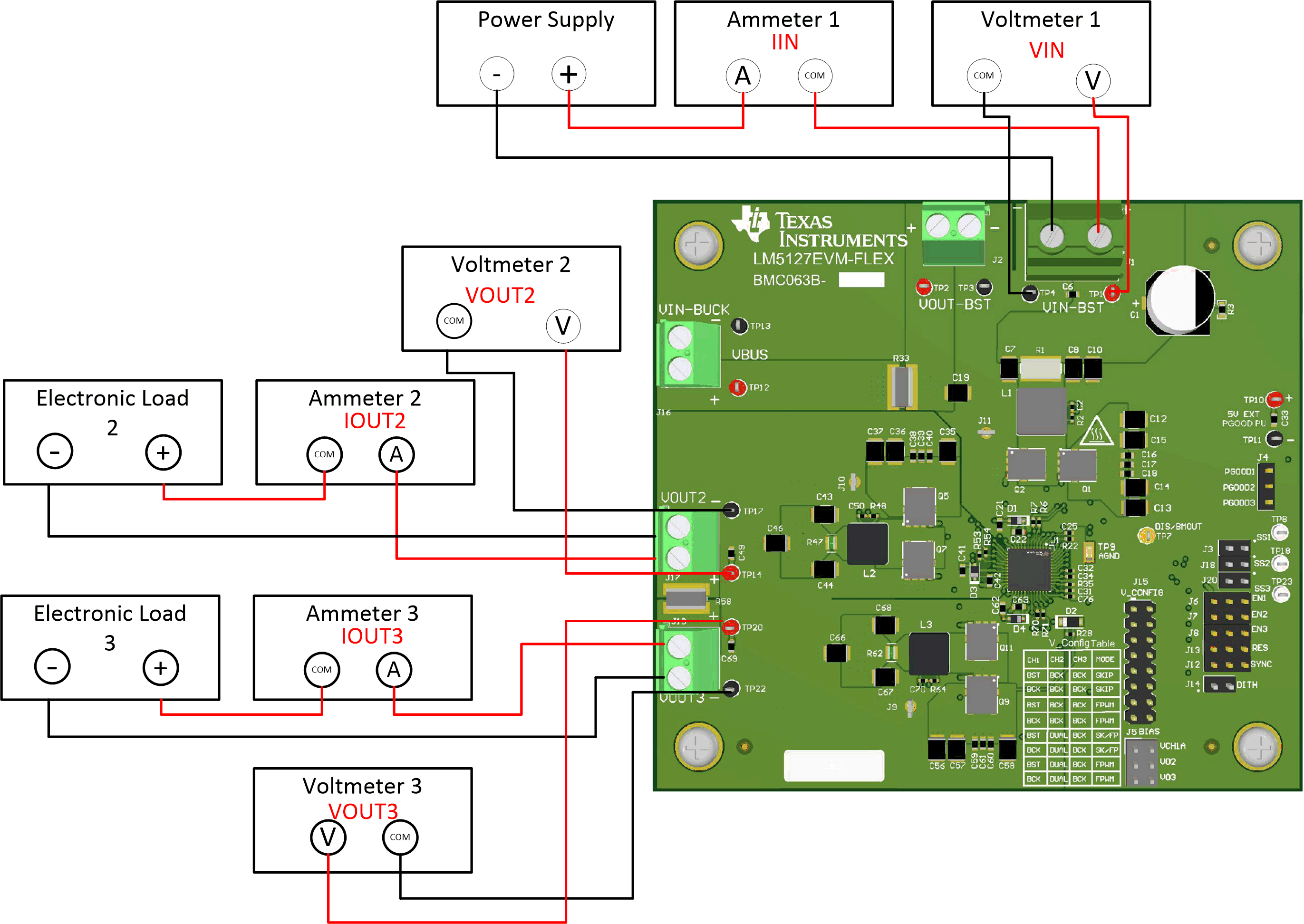
The following test equipment is needed to test the LM5127EVM-FLEX as shown in the Figure 4-1 and in the standard configuration according to Section 6.
- Power supply: The input voltage source (VIN) should be a variable supply. The power supply should source 3 V to 42 V and be able to supply more than 30 A or current.
- Electronic Load
- Electronic load 2: Capable of at least 5 A at a voltage of 5 V
- Electronic load 3: Capable of at least 7 A at a voltage of 3.3 V
- Multimeters
- Voltmeter 1 (VIN): Capable of measuring the input voltage range up to 42 V
- Voltmeter 2 (VOUT2): Capable of measuring output voltage of 5 V
- Voltmeter 3 (VOUT3): Capable of measuring output voltage of 3.3 V
- Ammeter 1 (IIN): Capable of 30 A DC measurement. A shunt resistor may also be used to measure the input current.
- Ammeter 2 (IOUT2): Capable of at least 5 A DC measurement
- Ammeter 3 (IOUT3): Capable of at least a 7 A DC measurement
 Figure 4-1 EVM Test Setup