SLVUBX9 October 2020
4.4.3 Current Limit and Fault Responses Test
Follow the instructions to verify the current limit and various fault response modes like auto-retry, latch and circuit breaker with auto-retry:
- Set up the oscilloscope as listed in Table 4-8.
Table 4-8 TPS2640EVM Oscilloscope Setting for the Current Limit Test
Oscilloscope Setting CH1 Probe Points CH2 Probe Points Channel 1 = 10V / div VOUT1 (TP3) VOUT2 (TP12) Channel 2 = 10V / div VIN1 (TP2) VIN2 (TP11) Channel 4 = 2 A / div Input current into T1 +Ve wire Input current into T3 +Ve wire Trigger source = Channel 2 Trigger level = 12 V ±1V Trigger polarity = Rising Trigger mode = Single Time base 100 ms / div Note:Measuring the current limit value on the oscilloscope can easily cause ±10% error from the typical expected values as listed in Table 4-9.
- Set the current limit to 2.23 A by installing the J5/J12 jumper in position 1-2.
- The jumper setting for different current limits is shown in Table 4-9.
- Set the current limit response to auto-retry by installing the J4/J11 jumper in
position 2-3. Table 4-9 TPS2640EVM Jumper Setting for Current Limits
CH1, CH2 Jumper Positions (J5, J12) Load Current Limit (A) 1-2 2.23 3-4 1.5 5-6 1 7-8 0.2 - Set the load resistance to 6 Ω ±1 Ω and the power supply voltage to 24 V.
- Enable the load.
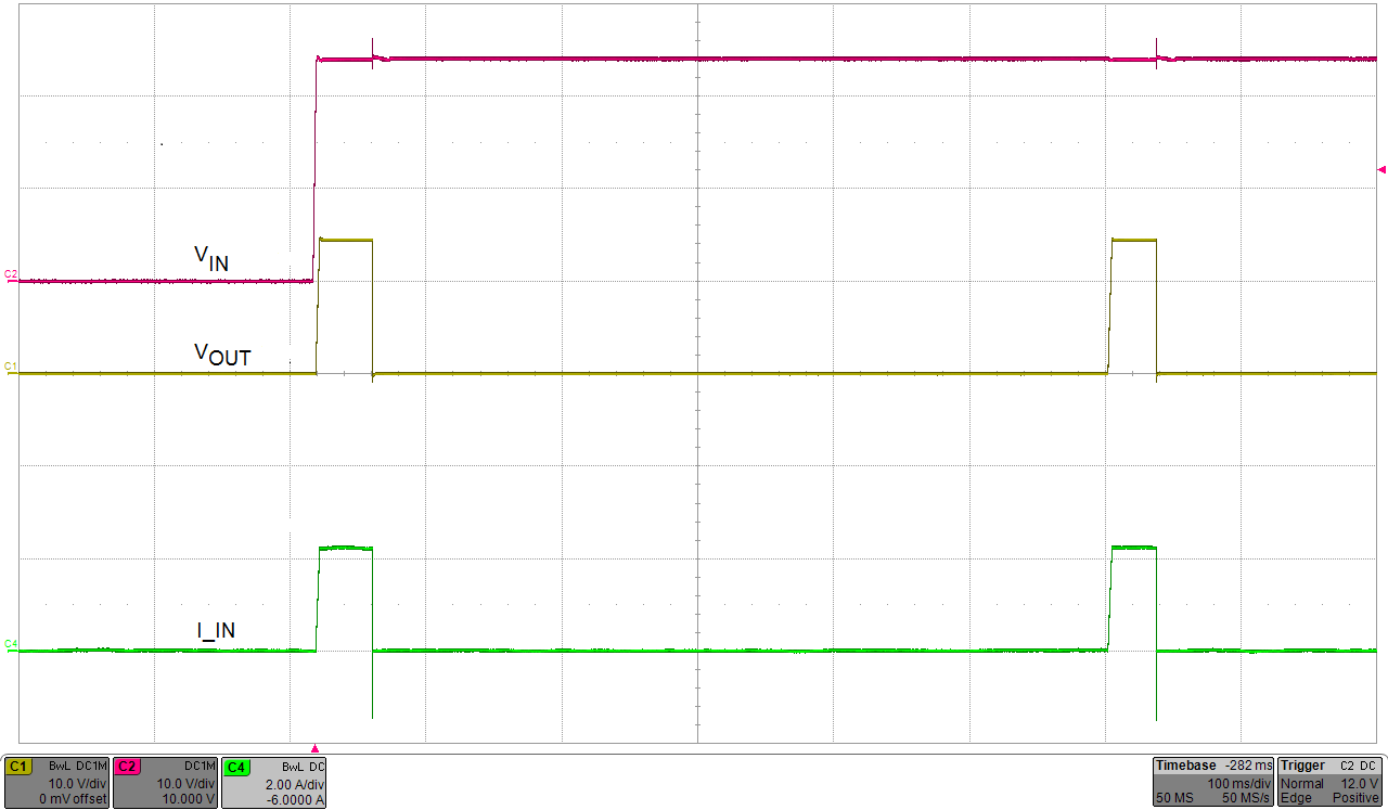
- Enable the power supply and verify the current limit
magnitude and auto-retry fault response waveform as shown in Figure 4-3.
 Figure 4-3 J5/J12 = 2-3 Position, Current Limit (2.23 A), Auto-Retry Mode
 - Disable the power supply.
- Set the current limit response mode to latch-off by installing the J4/J11 jumper in the position 1-2.
- Set the load resistance to 6 Ω ±1 Ω and enable the load.
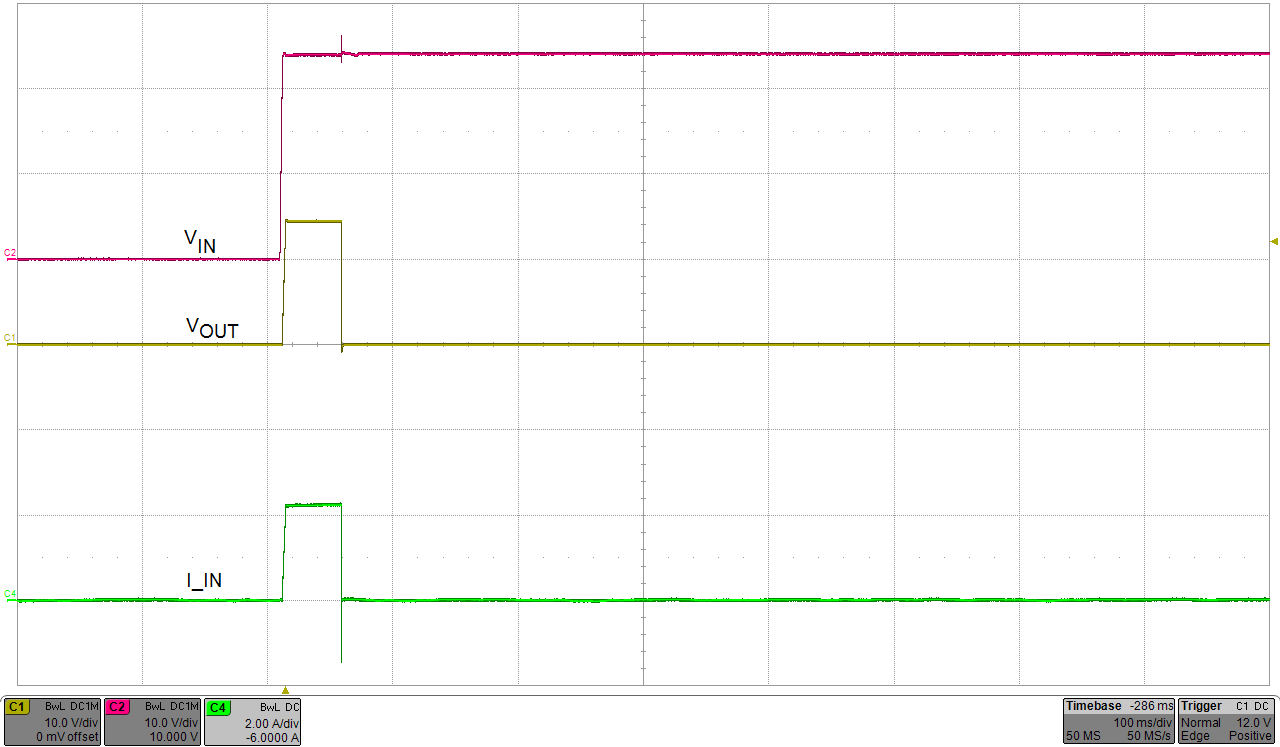
- Enable the power supply and verify the current limit magnitude the latch-off
fault response waveform as shown in the Figure 4-4.
 Figure 4-4 J5/J12 = 1-2 Position, Current Limit (2.23 A), Latch-Off Mode
 - Once the device is latched-off, either the power supply or the SHDNb should be recycled to re-enable it.
- Change the load resistance to 16 Ω ±1 Ω.
- Press and release the reset switch (S1/S2) to
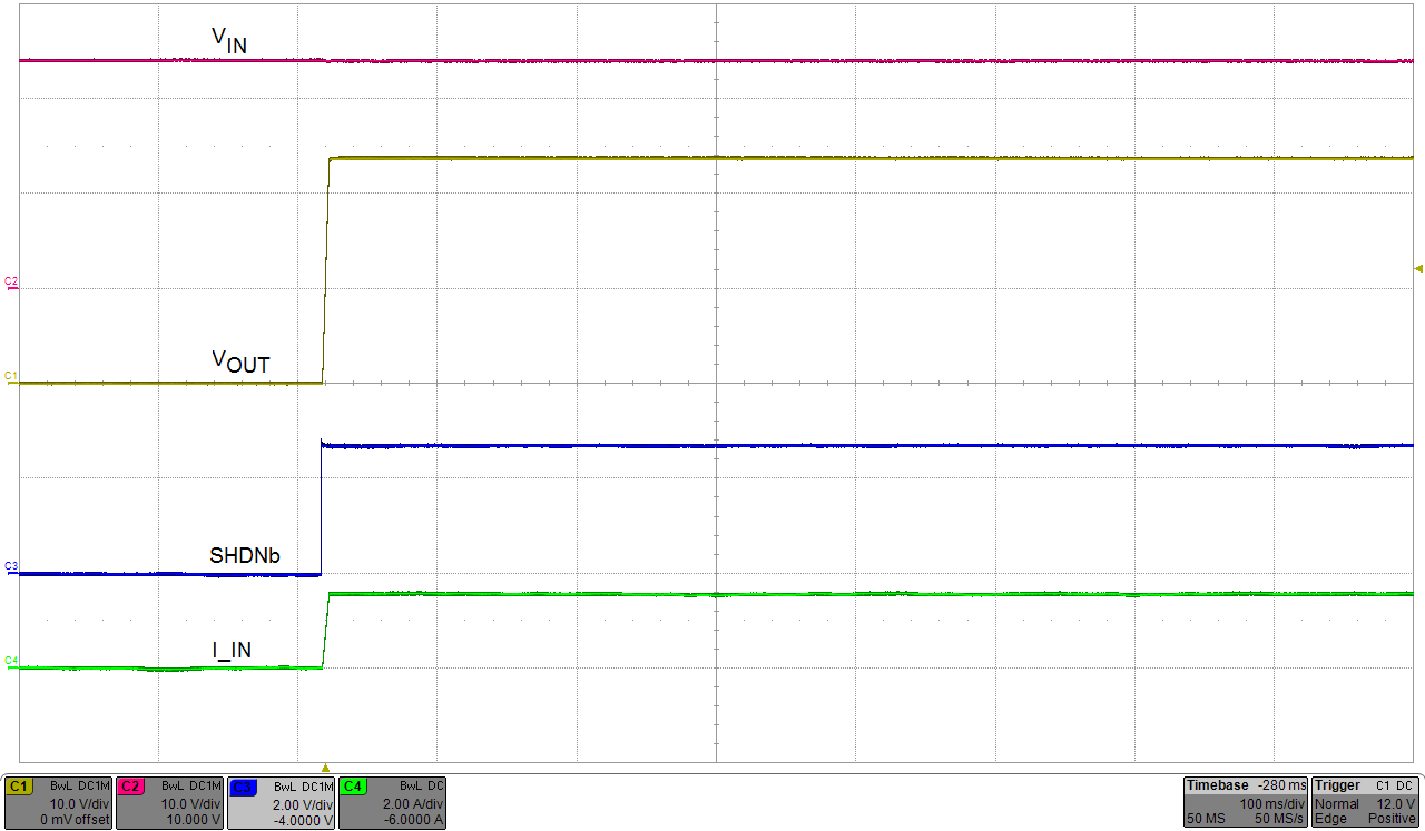
re-enable the device from latch-off mode and verify the recovery or restart
waveform as shown in Figure 4-5.
 Figure 4-5 Restart From Latch-Off Mode
 - Disable the power supply.
- Set the current limit response mode to circuit breaker with auto-retry by uninstalling the J4/J11 jumper.
- Set the load resistance to 6 Ω ±1 Ω and enable the load.
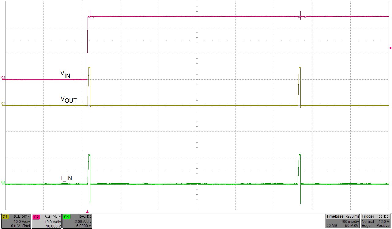
- Enable the power supply and verify the circuit breaker
with auto retry fault response waveform as shown in Figure 4-6.
 Figure 4-6 J5/J12 = Floating, Current Limit (2.23 A), Circuit Breaker With
Auto-Retry Mode