SLVU944B October 2015 – October 2020
4.1 EVM Layout Flexibility
The EVM is layed out to provide flexibility for the customer evaluation thus providing test points and or cold nose probes to monitor various critical nodes of the design as highlighted in the schematic.
Additionally, placeholder is provided thus one can add esr in series with the output capacitor (R47 in series with C39) thus making it easier to evaluate performance with increased capacitor esr.
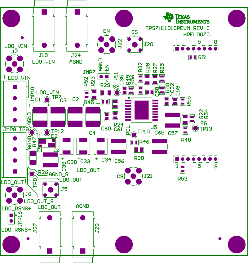 Figure 4-1 Component Placement (Top Side)
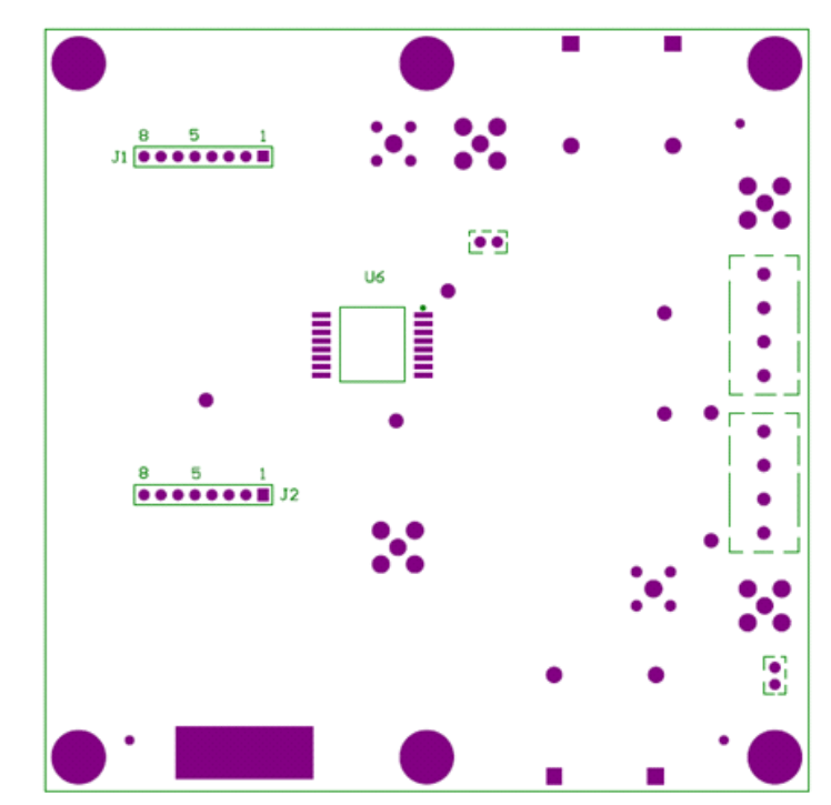 Figure 4-2 Component Placement (Bottom Side)
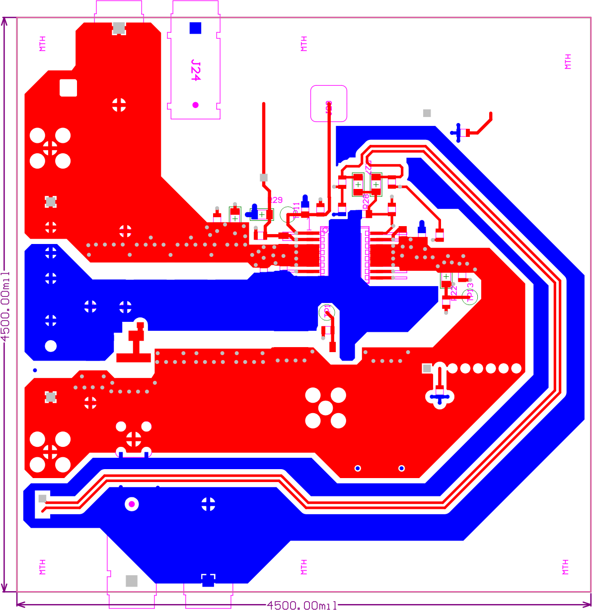 Figure 4-3 PCB Layout (Top Layer)
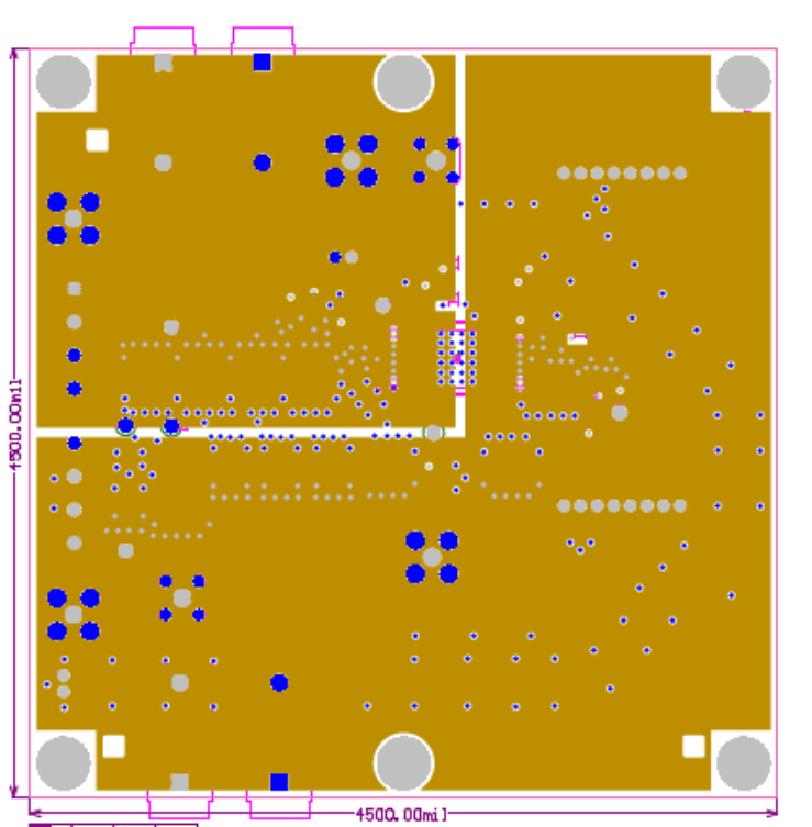 Figure 4-4 Board Layout - Second Layer (Mid Layer 1)
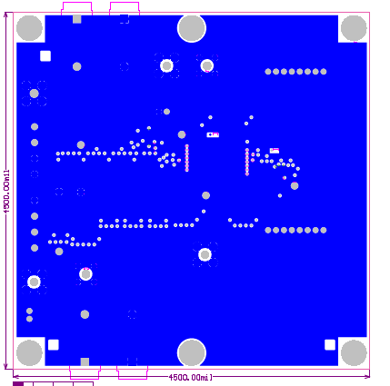 Figure 4-5 Board Layout - Third Layer (Mid Layer 2)
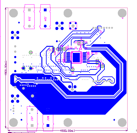 Figure 4-6 Board Layout - Fourth Layer (Bottom Layer)