SLVU944B October   2015  – October 2020 TPS7H1101-SP


  1.   Trademarks
  2. 1Introduction
    1. 1.1 Related Documentation
  3. 2Description
  4. 3Test Setup
    1. 3.1 Equipment
      1. 3.1.1 Power Supplies
      2. 3.1.2 Load Number 1
      3. 3.1.3 Meters
      4. 3.1.4 Oscilloscope
    2. 3.2 Bench Test Setup Conditions
      1. 3.2.1 Headers Description and Jumper Placement
      2. 3.2.2 Testing
    3. 3.3 Power-Up Procedure
      1. 3.3.1  IOUT and VOUT Measurements
      2. 3.3.2  Output Current Limiting
      3. 3.3.3  High-Side Current Sense
      4. 3.3.4  Current Foldback
      5. 3.3.5  Power Good
      6. 3.3.6  Dropout Voltage
      7. 3.3.7  Transient Response
      8. 3.3.8  Current Sharing
      9. 3.3.9  Soft-Start
      10. 3.3.10 Enable and Disable
      11. 3.3.11 Turn-Off
  5. 4Board Layout
    1. 4.1 EVM Layout Flexibility
  6. 5Schematic and Bill of Materials
  7.   Revision History

IOUT and VOUT Measurements

  1. Make sure all power supplies in workstation are OFF.
  2. Locate connectors J19 and J24.
  3. Connect VIN(+) to J19 and V(GND) to J24. Set it to 2.3 V.
  4. Locate measure points TP7 and TP12.
  5. Connect voltmeter: VIN(+) to TP7 and V(GND) to TP12.
  6. Locate connectors J27 and J28 and connect load here (be aware of polarities).
  7. Locate measure points TP8 and TP9.
  8. Connect voltmeter: VOUT(+) to TP8 and V(GND) to TP9.
  9. Output voltage should be per Table 2-1. This is done by setting R27 = 19.8 kΩ and R28 = 10 kΩ.

    VOUT can be determined by equation highlighted below or per equation 1 in the data sheet.

    Equation 1. GUID-B52F8ACC-ED33-4517-963A-37871327FF50-low.gif

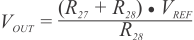
    Where VREF = 0.605 V.