SLVU944B October 2015 – October 2020
3.3.2 Output Current Limiting
A resistor value R30 connected from PCL pin to GND determines the output current limit set point based on Equation 2.
Maximum programmable current limit is 3800 mA.
Equation 2. 

Where VREF = 0.605 V, Icl = programmable current limit (A), CSR = Current sense ratio (typical value = 52000).
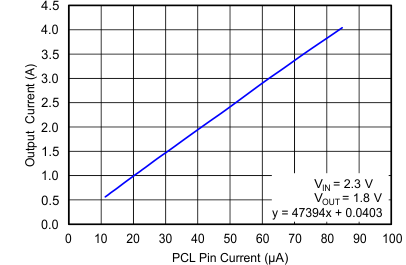
CSR between Ics pin and IOUT can be measured as shown in Figure 3-2.
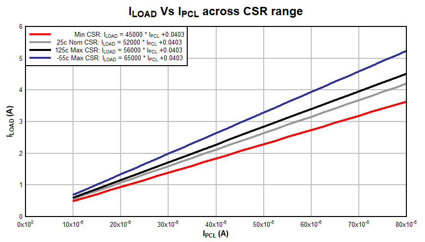
See Figure 3-3 for device Iload vs PCL pin current ranges.
- Make sure all power supplies in workstation are OFF.
- Connect VIN(+) to J19 & V(GND) to J24 and set it to 2.3 V.
- Set VOUT to 1.8V. (R27 = 19.8 kΩ and R28 = 10 kΩ)
- Connect load as previously instructed, set it to zero load.
- Increase Iload (steps of 0.100 A are suggested) until Vload starts to drop.
- Current limit trip point < 3.8 A.
 Figure 3-2 IOUT (A) vs
IPCL (uA)
 Figure 3-3 IOUT (A) vs IPCL (A) across CSR range