SLVU944B October   2015  – October 2020 TPS7H1101-SP


  1.   Trademarks
  2. 1Introduction
    1. 1.1 Related Documentation
  3. 2Description
  4. 3Test Setup
    1. 3.1 Equipment
      1. 3.1.1 Power Supplies
      2. 3.1.2 Load Number 1
      3. 3.1.3 Meters
      4. 3.1.4 Oscilloscope
    2. 3.2 Bench Test Setup Conditions
      1. 3.2.1 Headers Description and Jumper Placement
      2. 3.2.2 Testing
    3. 3.3 Power-Up Procedure
      1. 3.3.1  IOUT and VOUT Measurements
      2. 3.3.2  Output Current Limiting
      3. 3.3.3  High-Side Current Sense
      4. 3.3.4  Current Foldback
      5. 3.3.5  Power Good
      6. 3.3.6  Dropout Voltage
      7. 3.3.7  Transient Response
      8. 3.3.8  Current Sharing
      9. 3.3.9  Soft-Start
      10. 3.3.10 Enable and Disable
      11. 3.3.11 Turn-Off
  5. 4Board Layout
    1. 4.1 EVM Layout Flexibility
  6. 5Schematic and Bill of Materials
  7.   Revision History

Enable and Disable

EVM can be disabled via pulling the enable pin low via shorting JMP7-1 (Enable) to JMP7-2 (GND). Enable pin is tied high to VIN via R24 ( 20 kΩ) resistor, thus keeping the EVM enabled.

Alternately, EVM can also be disabled via pulling SS pin (U6 pin 1) low via an external circuit comprising of 2N7002 MOSFET as shown in Figure 3-11. A high signal at the gate of Q100 will discharge the SS pin and disable the device.
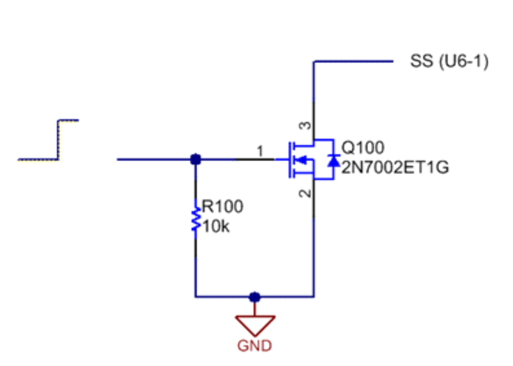
GUID-FAE87C0A-6776-4E06-A45A-3139A83CC8D5-low.pngFigure 3-11 Disabling the LDO via Soft-Start Pin