SLVAEX3 October 2020 TPS8802 , TPS8804
2.3.3 LED Current and Pulse Width
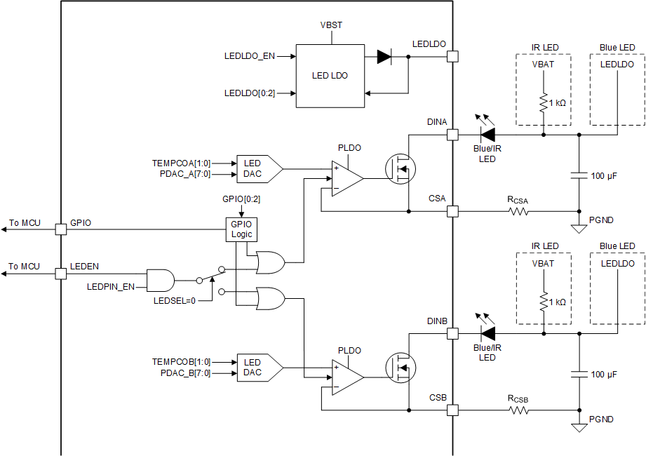
 Figure 2-3 TPS880x LED Driver Schematics
Increasing the LED current and pulse width improves the SNR at the cost of increased power consumption. LED current directly increases the LED output intensity and the smoke sensitivity of the detector. Increasing the LED current is a simple and effective way to increase the SNR.
Increasing the LED pulse width improves the SNR by allowing the photodiode current to be amplified for more time. Table 2-1 demonstrates the improvement in configurations 1 and 3 and configurations 4 and 8, where tLED is the LED pulse width. Increasing the LED pulse width and proportionally decreasing the amplifier speed also improves the SNR, shown in configurations 1 and 8.
For battery operated smoke detectors, increasing the LED current or pulse width may not be possible due to limited system power capacity. In this case, the LED current can be increased and the pulse width decreased to improve SNR while consuming the same amount of power. The benefit is small but evident when comparing configurations 1 and 4. The SNR and power consumption in configuration 1 is about half of configuration 4. If the LED current is doubled in configuration 1, the power consumption is the same as configuration 4 and the SNR is slightly higher than configuration 4. Since the 50 µs pulse width was tested with only one τ1 and τ2 combination, it is likely that the SNR of configuration 1 can be improved by varying τ1 and τ2.
If multiple ADC samples are taken, fewer top ADC samples can be taken with shorter pulse widths. This may reduce the benefit of using a shorter pulse width. Always take measurements to confirm the SNR improvement when modifying system parameters.
Increasing the LED current increases the LED forward voltage and the LED power consumption. The LED power consumption is equal to the LED current times the LED forward voltage. Because the TPS880x uses a linear regulating LED driver, the power consumed by the driver and LED is equal to the LED current times the LED supply voltage. In applications where the SNR is too low and power consumption must be minimized, it is optimal to first increase the LED current until a higher LED supply voltage is required, then increase the LED pulse width. At high LED currents, the LED output power per input current and lifespan drops.
The TPS880x LED driver has a propagation delay and rise time that limits the minimum pulse width. It is recommended to use a pulse width longer than 20 microseconds to mitigate propagation delay and rise time variation effects on the signal.