SLUAAB9A March 2021 – December 2021 UCC25800-Q1
- Trademarks
- 1 Introduction
- 2 Open-Loop LLC Converter Operation Principle
- 3 Primary-side and Secondary-side Resonant Configurations
- 4 Rectification Methods
- 5 LLC Transformer Design Steps
- 6 Negative Voltage Generation
- 7 Multiple-output Design
- 8 EMI Performance
- 9 Common-Mode Transient Immunity (CMTI)
- 10Summary
- 11Revision History
2 Open-Loop LLC Converter Operation Principle
Different from the typical PWM converters, LLC converters adjust the output voltage through varying its switching frequency. It is often called a PFM (Pulse Frequency Modulation) converter. As shown in Figure 2-1, the LLC converter has three resonant elements, the resonant inductor (Lr), the magnetizing inductor (Lm), and the resonant capacitor (Cr). In isolated bias supply designs, the transformer leakage inductance, and the magnetizing inductor can be used as part of the resonant circuit. The only external resonant component is the resonant capacitor.
The resonant frequency of the LLC converter is defined by the series resonance between the resonant inductor (Lr) and the resonant capacitor (Cr), as shown in Equation 1
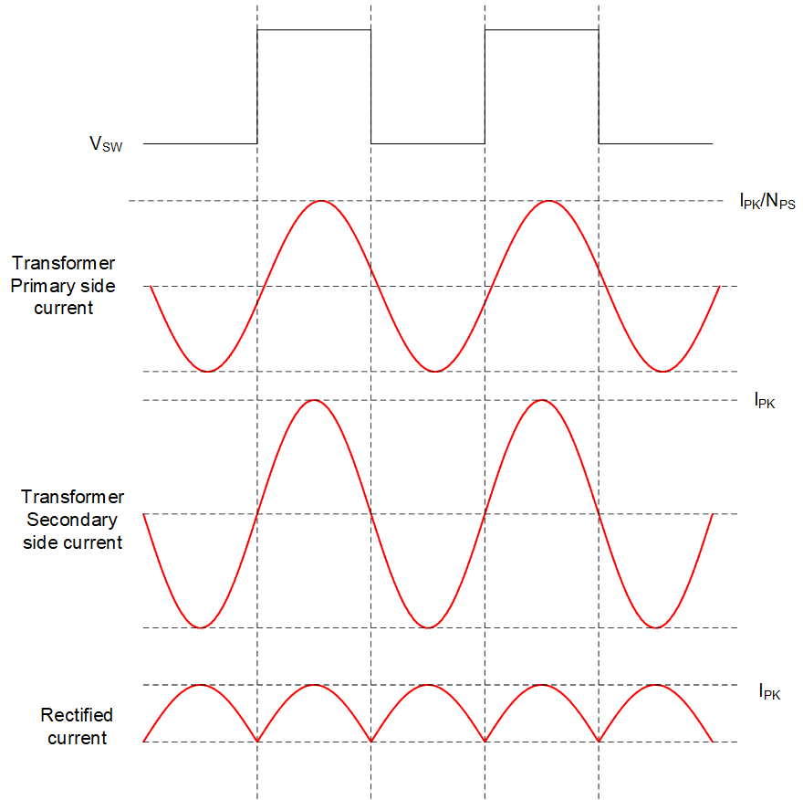
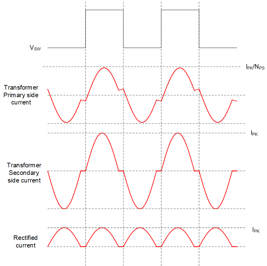
When its switching frequency is equal or below the resonant frequency, the operation waveforms of LLC converter can be found in Figure 2-2.
When the switching frequency is equal to the resonant frequency, it can be observed that the transformer primary-side current is a sinusoidal shape. The secondary-side current is also a sinusoidal shape but with some phase shift to the primary side current. The phase shift is caused by the transformer magnetizing current. The output current is equal to the rectified transformer secondary-side current. In this operation mode, the resonant tank impedance is equal to zero, and the input and output voltages are connected virtually through the transformer. When the switching frequency moves away from the resonant frequency, the impedance of the resonant tank increases. As a result, the output voltage reduces. However, this only holds true when the switching frequency is higher than the resonant frequency, because the magnetizing inductor never participates the resonant and it doesn't influence the characteristic performance of the resonant circuit.
When the switching frequency is below the resonant frequency, it can be observed that the sinusoidal current becomes discontinuous. In the duration where the sinusoidal shape stops, transformer secondary-side current is equal to zero. During this period, the magnetizing inductor becomes part of the resonant circuit, but the resonant frequency is so low that the current shape appears linear. During this period, the magnetizing inductor stores more energy and transfers it to the secondary side through the resonant capacitor in the following half switching cycle. Therefore, the LLC is able to achieve higher voltage gain.
 |
 |
| (a) Switching frequency is equal to resonant frequency | (b) Switching frequency is below resonant frequency |
The LLC converter voltage gain refers to the relationship between its output voltage and its input voltage. It is defined as Equation 2. In this equation, n is the transformer primary side to secondary side turns ratio and the ½ comes from the half bridge configuration.
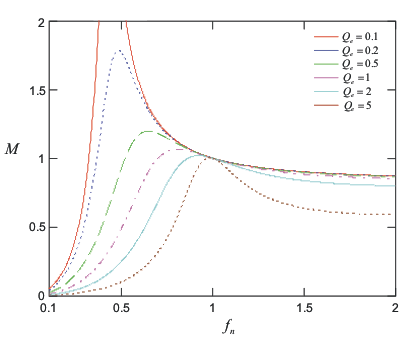
As shown in Figure 2-3, the voltage gain is affected by both switching frequency and load. In this set of curves, the switching frequency is normalized with the resonant frequency, which is defined in Equation 1, and Equation 3. The load can be normalized with the characteristic impedance and defined as Equation 4. Here, fs is the switching frequency.
 Figure 2-3 LLC Converter Voltage Gain
From this set of gain curves, at the resonant frequency, regardless of load conditions, the converter has a gain equal to 1, which means the relationship between the input and output voltage is only determined by the transformer turns ratio. This can be simply understood by the impedance of the resonant tank (Lr and Cr) is equal to zero at the resonant frequency. The input and output voltages are directly connected together virtually through the transformer.
If the LLC converter operates with a fixed switching frequency equal to the resonant frequency, the LLC converter is able to deliver a fixed voltage gain, with different load conditions. With a fixed input voltage, a fixed output voltage can be achieved.